
Installation guide
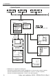

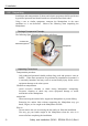

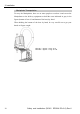
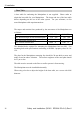
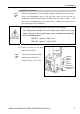
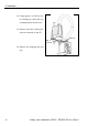
Table Of Contents
- EM135B2511F Robot System Safety and Installation Read this manual first (RC90/RC+5.0) Rev.6
- PREFACE
- TABLE OF CONTENTS
- 1. Safety 1
- 2. Installation 19
- System Example 20
- 2.1 Outline from Unpacking to Operation of Robot System 21
- 2.2 Unpacking 22
- 2.3 Transportation 23
- 2.4 Manipulator Installation 25
- 2.5 Controller Installation 29
- 2.6 Connection to EMERGENCY Connector (Controller) 31
- 2.7 Power Supply 38
- 2.8 Connecting Manipulator and Controller 40
- 2.9 Power-on 41
- 2.10 Saving Default Status 43
- 3. First Step 44
- 4. Second Step 57
- 5. General Maintenance 59
- 6. Manuals 64
- 7. Directives and Norms 66
- 1. Safety
- 1.1 Conventions
- 1.2 Design and Installation Safety
- 1.3 Operation Safety
- 1.4 Maintenance Safety
- 1.5 Emergency Stop
- 1.6 Labels
- 1.7 Safety Features
- Emergency Stop Switch
- Safety Door Input
- Low Power Mode
- Dynamic Brake
- Motor Overload Detection
- Irregular Motor Torque (out-of-control manipulator) Detection
- Motor Speed Error Detection
- Positioning Overflow -Servo Error- Detection
- Speed Overflow -Servo Error- Detection
- CPU Irregularity Detection
- Memory Check-sum Error Detection
- Overheat Detection at the Motor Driver Module
- Relay Deposition Detection
- Over-Voltage Detection
- AC Power Supply Voltage Drop Detection
- Temperature Anomaly Detection
- Fan Malfunction Detection
- 1.8 Lockout / Tagout
- 2. Installation
- System Example
- 2.1 Outline from Unpacking to Operation of Robot System
- 2.2 Unpacking
- 2.3 Transportation
- 2.4 Manipulator Installation
- 2.5 Controller Installation
- 2.6 Connection to EMERGENCY Connector (Controller)
- 2.7 Power Supply
- 2.8 Connecting Manipulator and Controller
- 2.9 Power-on
- 2.10 Saving Default Status
- 3. First Step
- 4. Second Step
- 5. General Maintenance
- 6. Manuals
- 7. Directives and Norms
2. Installation
Safety and Installation (RC90 / EPSON RC+5.0) Rev.6
27
Installation Procedure
When the Manipulator is Clean-model, unpack it outside of the clean room.
)
NOTE
Secure the Manipulator not to fall, and then wipe off the dust on the
Manipulator with a little alcohol or distilled water on a lint-free cloth. After
that, carry the Manipulator in the clean room. Connect an exhaust tube to
the exhaust port after installation.
CAUTION
■
Install the LS series Manipulator with two or more people.
The Manipulator weights are as follows. Be careful not to get
hands, fingers, or feet caught and/or have equipment damaged by
a fall of the Manipulator.
LS3-401* : approx. 14 kg: 31 lb.
LS6-602* : approx. 17 kg: 37.5 lb.
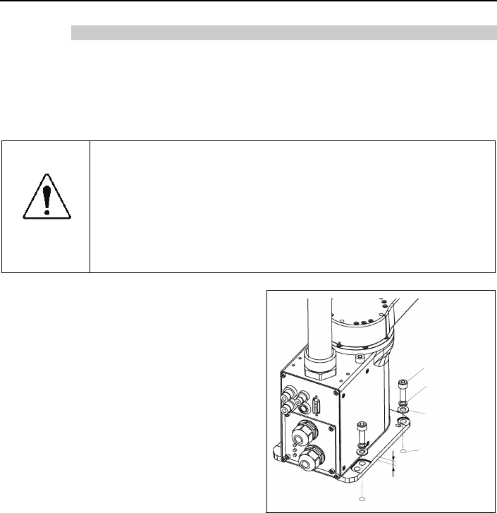
10 mm
4-M8
×
25
Screw Hole
(depth 20 m m
or more)
Spring
Washer
Plan e
Washer
(1) Secure the base to the base
table with four bolts.
Use bolts with specifications
conforming to ISO898-1
Property Class: 10.9 or 12.9.
)
NOTE