
Installation guide
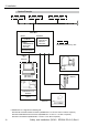

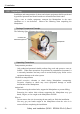

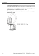
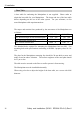
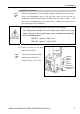
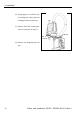
Table Of Contents
- EM135B2511F Robot System Safety and Installation Read this manual first (RC90/RC+5.0) Rev.6
- PREFACE
- TABLE OF CONTENTS
- 1. Safety 1
- 2. Installation 19
- System Example 20
- 2.1 Outline from Unpacking to Operation of Robot System 21
- 2.2 Unpacking 22
- 2.3 Transportation 23
- 2.4 Manipulator Installation 25
- 2.5 Controller Installation 29
- 2.6 Connection to EMERGENCY Connector (Controller) 31
- 2.7 Power Supply 38
- 2.8 Connecting Manipulator and Controller 40
- 2.9 Power-on 41
- 2.10 Saving Default Status 43
- 3. First Step 44
- 4. Second Step 57
- 5. General Maintenance 59
- 6. Manuals 64
- 7. Directives and Norms 66
- 1. Safety
- 1.1 Conventions
- 1.2 Design and Installation Safety
- 1.3 Operation Safety
- 1.4 Maintenance Safety
- 1.5 Emergency Stop
- 1.6 Labels
- 1.7 Safety Features
- Emergency Stop Switch
- Safety Door Input
- Low Power Mode
- Dynamic Brake
- Motor Overload Detection
- Irregular Motor Torque (out-of-control manipulator) Detection
- Motor Speed Error Detection
- Positioning Overflow -Servo Error- Detection
- Speed Overflow -Servo Error- Detection
- CPU Irregularity Detection
- Memory Check-sum Error Detection
- Overheat Detection at the Motor Driver Module
- Relay Deposition Detection
- Over-Voltage Detection
- AC Power Supply Voltage Drop Detection
- Temperature Anomaly Detection
- Fan Malfunction Detection
- 1.8 Lockout / Tagout
- 2. Installation
- System Example
- 2.1 Outline from Unpacking to Operation of Robot System
- 2.2 Unpacking
- 2.3 Transportation
- 2.4 Manipulator Installation
- 2.5 Controller Installation
- 2.6 Connection to EMERGENCY Connector (Controller)
- 2.7 Power Supply
- 2.8 Connecting Manipulator and Controller
- 2.9 Power-on
- 2.10 Saving Default Status
- 3. First Step
- 4. Second Step
- 5. General Maintenance
- 6. Manuals
- 7. Directives and Norms
2. Installation
2.2 Unpacking
Installation and transportation of robots and robotic equipment shall be performed
by qualified personnel and should conform to all national and local codes.
Using a cart or similar equipment, transport the Manipulator in the same
conditions as it was delivered. Observe the following when unpacking the
Manipulator.
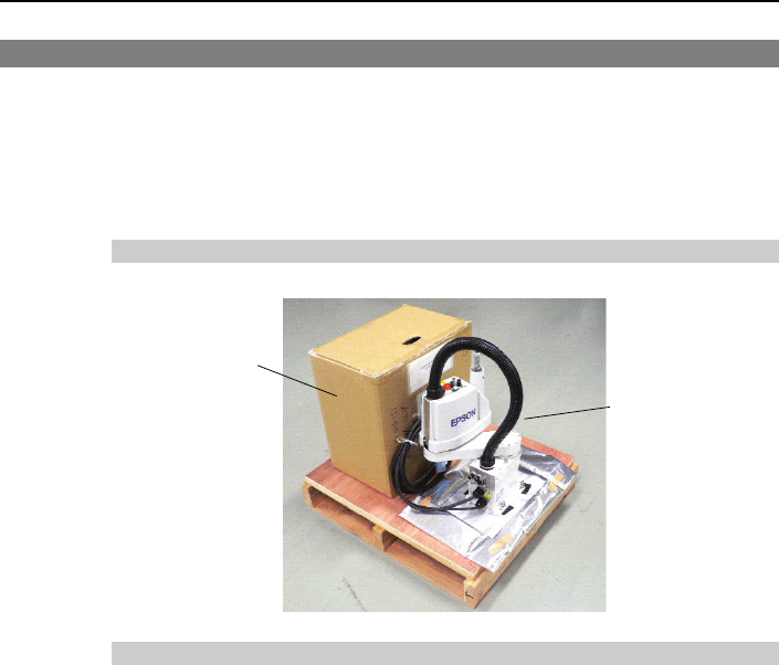
Package Components Example
The following figure illustrates the package at delivery.
Manipulator
Controller etc.
A
ttached Equipment
Unpacking Precautions
Transportation procedure
: Only authorized personnel should perform sling work and operate a crane or
forklift. When these operations are performed by unauthorized personnel, it
is extremely hazardous and may result in serious bodily injury and/or severe
equipment damage to the robot system.
Vibration at transportation
: Avoid excessive vibration or shock during Manipulator transporting.
Excessive vibration or shock may cause equipment damage to and/or
malfunction of the Manipulator.
Anchor bolt
: When removing the anchor bolts, support the Manipulator to prevent falling.
Removing the anchor bolts without supporting the Manipulator may get
hands, fingers, or feet caught as the Manipulator will fall.
Wire tie
: Do not remove the wire tie securing the arm until you finish the installation.
You may get your hands caught in the Manipulator when the wire tie is
removed before completing the installation.
Safety and Installation (RC90 / EPSON RC+5.0) Rev.6
22