
Installation guide
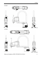
Table Of Contents
- EM135B2511F Robot System Safety and Installation Read this manual first (RC90/RC+5.0) Rev.6
- PREFACE
- TABLE OF CONTENTS
- 1. Safety 1
- 2. Installation 19
- System Example 20
- 2.1 Outline from Unpacking to Operation of Robot System 21
- 2.2 Unpacking 22
- 2.3 Transportation 23
- 2.4 Manipulator Installation 25
- 2.5 Controller Installation 29
- 2.6 Connection to EMERGENCY Connector (Controller) 31
- 2.7 Power Supply 38
- 2.8 Connecting Manipulator and Controller 40
- 2.9 Power-on 41
- 2.10 Saving Default Status 43
- 3. First Step 44
- 4. Second Step 57
- 5. General Maintenance 59
- 6. Manuals 64
- 7. Directives and Norms 66
- 1. Safety
- 1.1 Conventions
- 1.2 Design and Installation Safety
- 1.3 Operation Safety
- 1.4 Maintenance Safety
- 1.5 Emergency Stop
- 1.6 Labels
- 1.7 Safety Features
- Emergency Stop Switch
- Safety Door Input
- Low Power Mode
- Dynamic Brake
- Motor Overload Detection
- Irregular Motor Torque (out-of-control manipulator) Detection
- Motor Speed Error Detection
- Positioning Overflow -Servo Error- Detection
- Speed Overflow -Servo Error- Detection
- CPU Irregularity Detection
- Memory Check-sum Error Detection
- Overheat Detection at the Motor Driver Module
- Relay Deposition Detection
- Over-Voltage Detection
- AC Power Supply Voltage Drop Detection
- Temperature Anomaly Detection
- Fan Malfunction Detection
- 1.8 Lockout / Tagout
- 2. Installation
- System Example
- 2.1 Outline from Unpacking to Operation of Robot System
- 2.2 Unpacking
- 2.3 Transportation
- 2.4 Manipulator Installation
- 2.5 Controller Installation
- 2.6 Connection to EMERGENCY Connector (Controller)
- 2.7 Power Supply
- 2.8 Connecting Manipulator and Controller
- 2.9 Power-on
- 2.10 Saving Default Status
- 3. First Step
- 4. Second Step
- 5. General Maintenance
- 6. Manuals
- 7. Directives and Norms

1. Safety
16 Safety and Installation (RC90 / EPSON RC+5.0) Rev.6
CPU Irregularity Detection
Irregularity of CPU that controls the motor is detected by the watchdog timer.
The system CPU and the motor controlling CPU inside the Controller are also
designed to constantly check each other for any discrepancies. If a discrepancy is
detected, the dynamic brake circuit is activated.
Memory Check-sum Error Detection
The dynamic brake circuit is activated when a memory check-sum error is
detected.
Overheat Detection at the Motor Driver Module
The dynamic brake circuit is activated when the temperature of the power device
inside the Motor Driver module is above the nominal limit.
Relay Deposition Detection
The dynamic brake circuit is activated when relay deposition is detected.
Over-Voltage Detection
The dynamic brake circuit is activated when the voltage of the Controller is above
the normal limit.
AC Power Supply Voltage Drop Detection
The dynamic brake circuit is activated when the drop of the power supply voltage
is detected.
Temperature Anomaly Detection
The temperature anomaly is detected.
Fan Malfunction Detection
Malfunction of the fan rotation speed is detected.