
Installation guide
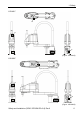
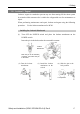
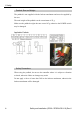
Table Of Contents
- EM135B2511F Robot System Safety and Installation Read this manual first (RC90/RC+5.0) Rev.6
- PREFACE
- TABLE OF CONTENTS
- 1. Safety 1
- 2. Installation 19
- System Example 20
- 2.1 Outline from Unpacking to Operation of Robot System 21
- 2.2 Unpacking 22
- 2.3 Transportation 23
- 2.4 Manipulator Installation 25
- 2.5 Controller Installation 29
- 2.6 Connection to EMERGENCY Connector (Controller) 31
- 2.7 Power Supply 38
- 2.8 Connecting Manipulator and Controller 40
- 2.9 Power-on 41
- 2.10 Saving Default Status 43
- 3. First Step 44
- 4. Second Step 57
- 5. General Maintenance 59
- 6. Manuals 64
- 7. Directives and Norms 66
- 1. Safety
- 1.1 Conventions
- 1.2 Design and Installation Safety
- 1.3 Operation Safety
- 1.4 Maintenance Safety
- 1.5 Emergency Stop
- 1.6 Labels
- 1.7 Safety Features
- Emergency Stop Switch
- Safety Door Input
- Low Power Mode
- Dynamic Brake
- Motor Overload Detection
- Irregular Motor Torque (out-of-control manipulator) Detection
- Motor Speed Error Detection
- Positioning Overflow -Servo Error- Detection
- Speed Overflow -Servo Error- Detection
- CPU Irregularity Detection
- Memory Check-sum Error Detection
- Overheat Detection at the Motor Driver Module
- Relay Deposition Detection
- Over-Voltage Detection
- AC Power Supply Voltage Drop Detection
- Temperature Anomaly Detection
- Fan Malfunction Detection
- 1.8 Lockout / Tagout
- 2. Installation
- System Example
- 2.1 Outline from Unpacking to Operation of Robot System
- 2.2 Unpacking
- 2.3 Transportation
- 2.4 Manipulator Installation
- 2.5 Controller Installation
- 2.6 Connection to EMERGENCY Connector (Controller)
- 2.7 Power Supply
- 2.8 Connecting Manipulator and Controller
- 2.9 Power-on
- 2.10 Saving Default Status
- 3. First Step
- 4. Second Step
- 5. General Maintenance
- 6. Manuals
- 7. Directives and Norms

1. Safety
14 Safety and Installation (RC90 / EPSON RC+5.0) Rev.6
1.7 Safety Features
The robot control system supports safety features described below. However, the
user is recommended to strictly follow the proper usage of the robot system by
thoroughly reading the attached manuals before using the system. Failure to read
and understand the proper usage of the safety functions is highly dangerous.
Among the following safety features, the Emergency Stop Switch and Safety Door
Input are particularly important. Make sure that these and other features function
properly before operating the robot system.
For details, refer to the 2.5 Controller Installation - Safety Door Switch and Latch
Release Switch.
Emergency Stop Switch
The EMERGENCY connector on the Controller has expansion Emergency Stop
input terminals used for connecting the Emergency Stop switches.
Pressing any Emergency Stop switch can shut off the motor power immediately
and the robot system will enter the Emergency Stop condition.
Safety Door Input
In order to activate this feature, make sure that the Safety Door Input switch is
connected to the EMERGENCY connector at the Controller.
When the safety door is opened, normally the Manipulator immediately stops the
current operation, and the status of Manipulator power is operation-prohibited
until the safety door is closed and the latched condition is released. In order to
execute the Manipulator operation while the safety door is open, you must change
the mode selector key switch on the Teach Pendant to the “Teach” mode.
Manipulator operation is available only when the enable switch is on. In this
case, the Manipulator is operated in low power status.