
Installation guide
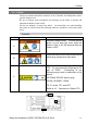
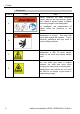
Table Of Contents
- EM135B2511F Robot System Safety and Installation Read this manual first (RC90/RC+5.0) Rev.6
- PREFACE
- TABLE OF CONTENTS
- 1. Safety 1
- 2. Installation 19
- System Example 20
- 2.1 Outline from Unpacking to Operation of Robot System 21
- 2.2 Unpacking 22
- 2.3 Transportation 23
- 2.4 Manipulator Installation 25
- 2.5 Controller Installation 29
- 2.6 Connection to EMERGENCY Connector (Controller) 31
- 2.7 Power Supply 38
- 2.8 Connecting Manipulator and Controller 40
- 2.9 Power-on 41
- 2.10 Saving Default Status 43
- 3. First Step 44
- 4. Second Step 57
- 5. General Maintenance 59
- 6. Manuals 64
- 7. Directives and Norms 66
- 1. Safety
- 1.1 Conventions
- 1.2 Design and Installation Safety
- 1.3 Operation Safety
- 1.4 Maintenance Safety
- 1.5 Emergency Stop
- 1.6 Labels
- 1.7 Safety Features
- Emergency Stop Switch
- Safety Door Input
- Low Power Mode
- Dynamic Brake
- Motor Overload Detection
- Irregular Motor Torque (out-of-control manipulator) Detection
- Motor Speed Error Detection
- Positioning Overflow -Servo Error- Detection
- Speed Overflow -Servo Error- Detection
- CPU Irregularity Detection
- Memory Check-sum Error Detection
- Overheat Detection at the Motor Driver Module
- Relay Deposition Detection
- Over-Voltage Detection
- AC Power Supply Voltage Drop Detection
- Temperature Anomaly Detection
- Fan Malfunction Detection
- 1.8 Lockout / Tagout
- 2. Installation
- System Example
- 2.1 Outline from Unpacking to Operation of Robot System
- 2.2 Unpacking
- 2.3 Transportation
- 2.4 Manipulator Installation
- 2.5 Controller Installation
- 2.6 Connection to EMERGENCY Connector (Controller)
- 2.7 Power Supply
- 2.8 Connecting Manipulator and Controller
- 2.9 Power-on
- 2.10 Saving Default Status
- 3. First Step
- 4. Second Step
- 5. General Maintenance
- 6. Manuals
- 7. Directives and Norms
1. Safety
Safety and Installation (RC90 / EPSON RC+5.0) Rev.6 11
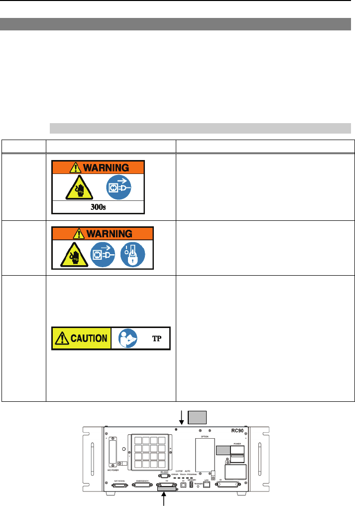
1.6 Labels
Labels are attached around the locations of the Controller and Manipulator where
specific dangers exist.
Be sure to comply with descriptions and warnings on the labels to operate and
maintain the Robot System safely.
Do not tear, damage, or remove the labels. Use meticulous care when handling
those parts or units to which the following labels are attached as well as the nearby
areas:
Controller
Location Label Note
A
Residual voltage exists. To avoid electric
shock, do not open the cover while the
Power is ON, or for 300 seconds after the
Power is OFF.
B
Disconnect and lockout main power before
performing maintenance and repair.
C
TP port of RC90 is for the Teach Pendant
TP2. Do not connect the followings to TP
port of RC90. Connecting to the
followings may result in malfunction of the
device.
OPTIONAL DEVICE dummy plug,
OP500, OP500RC, JP500,
TP-3** series, TP1, and OP1
Refer to 4.3 Connection of Option TP2.
A
C
B