Installation and Assembly: Advanced Projector Ceiling Mount with Precision Gear Model: ELPMBPRG R Distributed by: Epson America, Inc. 3840 Kilroy Airport Way Long Beach, CA 90806 www.epson.com This product is UL Listed. It must be installed by a qualified professional installer. Maximum UL Load Capacity: 50 lb (22.7 kg) Manufactured by Peerless Industries, Inc. 3215 W. North Ave. • Melrose Park, IL 60160 • (800) 865-2112 or (708) 865-8870 • Fax: (708) 865-2941 • www.peerlessmounts.
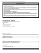
NOTE: Read entire instruction sheet before you start installation and assembly. WARNING • Do not begin to install your Peerless product until you have read and understood the instructions and warnings contained in this Installation Sheet. If you have any questions regarding any of the instructions or warnings, call Peerless customer care at 1-800-729-0307.
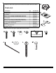
Before you start check the parts list to ensure all of the parts shown are included. A Parts List A B C D E F G H I J K L M Description projector mount assembly adapter plate side plate M4 x 20 mm socket pin serrated washer head screw M5 x 20 mm socket pin serrated washer head screw 3/8" spacer M4 x 6 mm socket pin serrated washer head screw #10-32 x 3/8'' socket pin serrated washer head screw 10-32 x 1/4'' socket pin screw with lock 4 mm security allen wrench washer #14 x 2.
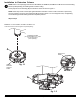
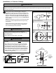
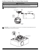
Installation to Extension Column 1 NOTE: Refer to accompanying instructions for ELPMBP01, ELPMBP02, ELPMBP03 or CMJ and ACC Series Ceiling Mounts (sold separately) for installing these models to ceiling. Screw projector mount assembly (A) onto extension column as shown in figure 1.1. NOTE: Swivel stop screw is used to jam against threads of extension column or flush mount tube to prevent any excess movement of projector mount assembly (A) as shown in detail 1.
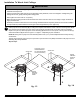
Installation To Wood Joist Ceilings WARNING • Installer must verify that the supporting surface will safely support the combined load of the equipment and all attached hardware and components. • Tighten wood screws so that projector mount assembly is firmly attached, but do not overtighten. Overtightening can damage the screws, greatly reducing their holding power. • Never tighten in excess of 80 in. • lb (9 N.M.). • Make sure that mounting screws are anchored into the center of the stud.
Installation to Concrete Ceilings WARNING • Concrete must be 2000 psi density minimum. Lighter density concrete may not hold concrete anchor. • Make sure that the supporting surface will safely support the combined load of the equipment and all attached hardware and components. 1 Place projector mount assembly (A) on ceiling as a template and mark the center of the two mounting holes. Drill two 1/4" (6 mm) dia. holes to a minimum depth of 2.5" (64 mm).
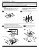
Installing Plates to Projector CAUTION • All spacers shall be used where indicated. Not using spacers can cause damage to projector. • It is the responsibility of the installer to ensure that the projector is properly ventilated. NOTE: For all POWERLITE models, the manufacturer's product weight must be reviewed to ensure that the weight does not exceed 50 lbs.
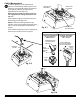
3 NOTE: Shoulder indicates back of adapter plate (B) Flip projector upside down. Find your projector model from the hole patterns listed below. Using the holes indicated on the corresponding hole pattern diagram, attach adapter plate (B) to projector using the appropriate number of M4 x 20 mm socket pin serrated washer head screws (D) and spacers (F). NOTE: For POWERLITE model 8300i, use M5 x 20 mm socket pin serrated washer head screws (E) in place of screws (D).
Installing Connection Block to Projector Mount Assembly WARNING • Always use an assistant or mechanical lifting equipment to safely lift and position the projector. 4 Slide connection block with projector into projector mount assembly (A) as shown. Tighten captive screw to secure projector to projector mount assembly (A).
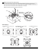
Cable Management 6 To make an opening to route cables through projector mount assembly, adjust projector mount assembly to full upward tilt position and maximum left or right roll position by turning knobs for adjustments as shown in figure 6.1. KNOB FOR ROLL ADJUSTMENT KNOB FOR TILT ADJUSTMENT NOTE: Be certain tamper resistant screws are not engaged before making adjustments (see step 7-1). Route cables through top of extension column as shown in figure 6.2 and figure 6.3.
Projector Alignment 7 To adjust yaw (swivel) for extension column installation: Loosen screw on projector mount assembly (A) indicated below until projector mount can be rotated. Rotate mount to desired position and retighten screw. To adjust pitch (forward and backward tilt): Turn knob on back of mount as shown below. Pull knob out and turn by hand for easy adjustment or insert #2 phillips screwdriver in end of knob and turn. To adjust roll (side to side tilt): Turn knob on side of mount as shown below.
Accessories NOTE: All accessories are available for purchase through Epson (www.epson.com) ELPMBP02 False Ceiling Plate Kit ELPMBP01 Adjustable Suspended Ceiling Channel Kit • Mounts above 2' x 2' or 2' x 4' ceiling tile to structural ceiling with tie wires • Includes tie wire supports and flush mount tube • 1 ½" - 11.5" NPT fitting for attachment of adjustable extension column • Two knockout panels for electrical outlet boxes • 13.