
Service manual


EPSON ELP-3500 Service Manual
2-11
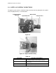
2.4 DRIVER BOARD
The driver board has a circuit for converting the signals from the main board into six
analog signal states and controlling the brightness and detecting the temperature. The
board can be replaced as a whole unit for maintenance service. The fuses on the board
are shown below.
Table 2-7.
Fuse Part Number Usage
F600 CCP2E20 +18 V (600 mA) Video AMP
F601 CCP2E20 +12 V (600 mA) DAC/Light Valve Driver
F602 CCP2E13 +5 V (520 mA) Control Circuits
F600
F601
F602
Figure 2-10.
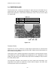
Functional Outline
Signals RT 0~7, GT 0~7, and BT 0~7, output from the main board, are converted into
analog signals by the digital to analog converter (DAC: IC601) before being output to the
driver circuit for the light valves.
Timing signals (for the monitor) output from the main board are converted into the signals
for the light valves (LCDs) by IC800 before outputting them. The sub-brightness circuit
modifies the output level of the R/G/B analog signals while controlling the lamp circuit for
the analog display signals.
The temperature detection circuit protects the circuit section from overheating. If the
temperature in the section rises more than a certain number of degrees, the circuit sends
an interrupt to the CPU on the main board.