
Service manual


EPSON ELP-3500 Service Manual
2-9
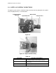
Functional Outline
* When power is turned on, the driver board activates the reset signal, which is
controlled by IC601, and the CPU reads the program from flash ROM and writes it into
RAM (IC303). Then the CPU sets the functions based on the program and projects
the initial image.
* The digital video interface (IC201) from the video board generates timing to project the
image data received or executes data bit conversion (A/D) to write the received
analog image data to SRAM.
* The memory controller (IC302) performs read/write operations, saving data to SRAM.
Video signals (analog/digital), provided through the interface board, are immediately
stored in video RAM.
* Data stored in SRAM is converted to analog signals by D/A converter. The output is
divided into 8 bits for each R/G/B light valve by the amplitude and lamp circuits.
* Digital R/G/B input signals are synchronized as image data, and the control timing is
stored in a three-state buffer before being output to the driver board.
* The analog R/G/B signal is amplified by the amplitude circuit and converted into
individual data signals of 7 bits each by A/D converter circuit before being output to
the driver board.
* Analog R/G/B output signals are transmitted in different ways for analog input and
digital input.
Analog R/G/B
Video amplitude is output via video buffer.
Digital R/G/B
The digital image signals (R 0 ~ 7 / G 0 ~ 7 / B 0 ~ 7) output from the driver board
are converted into analog signals by the chroma circuit and the D/A converter
before being output through the video buffer.
* Audio input volume is controlled (Loud/Quiet/Mute) by the audio control circuit and
amplified by the audio amplitude circuit before being output to the speaker unit
(Right/Left) through the driver board.
* The audio input signal is transferred to the audio output interface via the audio control
circuit.