
Service manual


EPSON ELP-3500 Service Manual
2-5
Functional Outline
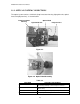
* The interlock switch at the bottom of main chassis shuts off AC power when the lamp
cover is opened. It is normally in the ON position.
* The cable connected to CN505 on the main board is a signal line to indicate the
conditions of two fans (the exhaust fan and intake fan), which are connected to
connectors CN503 and CN502 on the main board. These signals shut off power to the
light source lamp to prevent overheating if either fan stops rotating.
* The filter/rectification circuit reduces noise on the AC line and generates DC voltage
for the regulator.
* The regulator generates various DC voltage levels shown in the table below for the
switching regulator. The regulator detects the voltage output level on the +5 V line and
feeds the information back to the switching circuit to maintain a stable output level,
regardless load variations. Every output voltage level is not subject to adjustment.
Table 2-3.
OUTPUT VOLTAGE SPECIFICATION
+18 V +18 V ± 5% (17.1 to 18.9 V)
+12 V +12 V ± 5% (11.4 to 12.6 V)
+ 5 V + 5 V ± 5% ( 4.75 to 5.25 V)
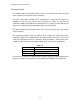
* The intake fan removes heat generated in the power supply unit. Heat expelled by the
intake fan is blown out by the exhaust fan, connected to CN503 on the main board.