
Service manual


EPSON ELP-3500 Service Manual
2-4
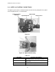
2.2 POWER SUPPLY UNIT
The power supply unit includes a DC regulator, exhaust fan, and interlock switch for the
lamp cover. This unit generates the voltages for the control circuit (+5 V, +12 V, +18 V)
and for the light source lamp (+65 V) from the AC input. Although a functional diagram is
shown below, never disassemble the power supply unit during field maintenance service.
Power Supply Unit
Figure 2-5.
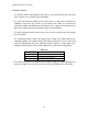
Functional Block Diagram
Figure 2-6.
* An interlock switch is included for safety purposes. The interlock switch shuts off the supply of AC power if
the lamp cover at the bottom of main chassis is opened.
* The safety switch input signal is designed for protection from overheating. It stops power output to the light
source lamp if the projector detects overheating in the lamp housing area.
REGULATORFILTER/
RECTIFIER
+12 V
+18 V
+5 V
+6.5 V
CONNECTIONS TO MAIN BOARD AND DRIVER BOARD
LAMP
EXHAUST FAN
MAIN
BOARD
CN505
SAFETY
SWITCH
(overheating
protection
)
POWER SWINTERLOCK SW
FUSE
250 V - 6.3 AAC IN
NC
NC