
Service manual


EPSON ELP-3500 Service Manual
2-2
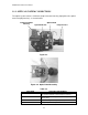
2.1.1 ELECTRICAL SYSTEM CONNECTIONS
Electrical units are physically connected to the main board, as shown below.
Figure 2-2.
Table 2-1.
UNIT NAME FUNCTIONS AND REMARKS
EXHAUST FAN
RECEPTOR BOARD
INTAKE FAN
POWER SUPPLY UNIT
MAIN BOARD BOARD
R/G/B LIGHT VALVE
SPEAKER UNIT
LIGHT SOURCE LAMP
DRIVER BOARD
INTERFACE UNIT
For eliminating heat from light source lamp and power supply unit
Remote control signal detection
Cools the lamp
Generates 65 V from AC IN for light source lamp
Generates +5 V / +12 V / +18 V
Projector function control (CPU, ROM, VRAM, light valve driver, others)
Generates image data (LCD panel)
Audio output
For image projection (metal halide discharge lamp)
A/D converter for analog video signal
Audio signal amplitude, others
External device connection
Control
Panel
IB2
IB1
Interface Unit
Intake Fan Receptor Board Speaker
Power Supply
Unit
Exhaust Fan
CN101
CN100
CN200
(opposite side)
CN503
CN505
CN502
CN501
CN600
CN950
CN504
CN400
CN900
Main Board
CN850
Light Valve B Light Valve G Light Valve R
Driver Board