
Service manual


EPSON ELP-3500 Service Manual
1-18
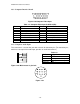
1.6.2 Computer Interface Board
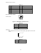
Figure 1-28.Computer Video Input
Table 1-7. Computer Video Input D-SUB 15 (HD)
Pin Signal Pin Signal
1 Red video 9 +5 V
2 Green video 10 Synchronous GND
3 Blue video 11 Monitor (ID bit 0)
4 Monitor (ID bit 2) 12 SDA
5 GND 13 Horizontal synchronization
6 Red video GND 14 Vertical synchronization
7 Green video GND 15 SCL
8 Blue video GND
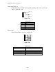
1.6.3 Computer Audio Input
This connector is a stereo mini jack with 2 circuits for detection pins (The detection pins,
which are not required for audio input, provides an audio out terminal.)
Table 1-8.
Pin No. Signal
1 GND
2 Computer audio input L
3 Computer audio input R
Other pins NC
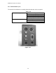
Figure 1-29. Multi-mouse 13-pin Jack
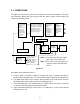
Figure 1-30.
1
2
3
4
5
6
7
8
9
4
8
14
1
5
9