Service Manual ELP-3500 www.electronicsrepair.net Epson America, Inc.
ELP-3500 Service Manual ii
INTRODUCTION This service manual describes hardware information necessary for field service and troubleshooting of the ELP-3500 Projector. Manual updates will be supplied in service bulletins. HOW TO USE THIS SERVICE MANUAL The manual covers topics required for field maintenance, so you can use it for diagnosis of failures or repair. Before beginning maintenance work, be sure to read and observe every safety precautions and all rules.
PRECAUTIONS OPERATOR SAFETY 1. PROTECTION FROM ELECTRIC SHOCK * Before performing any repair work on the product, be sure to turn off the power switch and remove the electric power cable from the electrical outlet.
* Use only the power cable and the interface cables supplied with the product. 3. OTHER PRECAUTIONS * Visually check for damage or dirt on the power connector and cable. If dirty, clean it, and if bent or damaged, replace the cable in to prevent firing by the flush over phenomenon. * When connecting internal connector cables or interface cables, be sure to plug them into the connector fully, until attached to the connector edge.
Contents Chapter 1 Product Features 1.1 Product Features ........................................................................................ 1-1 1.2 Parts of the Projector ................................................................................. 1-2 1.2.1 Exterior View of the Main Frame ....................................................... 1-2 1.2.2 Interior View of the Main Frame ........................................................ 1-4 1.2.3 Exterior View of the Remote Control ..........
Chapter 3 Disassembly and Assembly 3.1 Disassembly and Assembly Procedures .................................................... 3-1 3.2 Projector Main Unit Disassembly and Assembly ........................................ 3-3 3.2.1 Removing the Lamp Inner Housing................................................... 3-4 3.2.2 Removing the Upper Case Unit and Handle ..................................... 3-5 3.2.3 Removing the Air Filter Frame........................................................... 3-7 3.2.
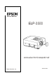
1.1 PRODUCT FEATURES The ELP-3500 Projector is an easy-to-use, portable presentation device with a VGA resolution that lets you project enhanced color images from personal computers and video equipment, such as VCRs, video camcorders, and video disc players. Figure 1-1. ❐ Portable, light-weight, compact The new power unit, circuit board design, and simple structure minimize the projector body almost to page-size length and width, and a weight of 14.8 lb (6.
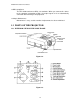
EPSON ELP-3500 Service Manual ❐ DDC compliance The ELP-3500 conforms to DDC 1/2 standards. When you connect this device to the computer conforming to DDC, the output signals of it are automatically converted into VGA images and projected. ❐ Simple Maintenance Maintenance is easy, and the number of adjustments has been minimized. 1.2 PARTS OF THE PROJECTOR 1.2.1 EXTERIOR VIEW OF THE MAIN FRAME Figure 1-2. Figure 1-3.
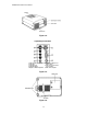
EPSON ELP-3500 Service Manual Figure 1-4. 1. VCR Syn-Video 6. Serial Port to Mouse Port 2. VCR Video (DB9 or PS/2) 3. VCR Audio Left 7. VGA Connection for Video 4. VCR Audio Right from Computer 5. Output for External Speakers 8. Audio from Computer Figure 1-5. Figure 1-6.
EPSON ELP-3500 Service Manual 1.2.2 INTERIOR VIEW OF THE MAIN FRAME Main Board Power Supply Safety Switch Figure 1-7. Driver Board Control Panel Speaker Interface Unit Projector Lens Figure 1-8.
EPSON ELP-3500 Service Manual 1.2.3 EXTERIOR VIEW OF THE REMOTE CONTROL Figure 1-9.
EPSON ELP-3500 Service Manual 1.2.4 INTERIOR VIEW OF THE REMOTE CONTROL Figure 1-10. Figure 1-11.
EPSON ELP-3500 Service Manual 1.3 CONNECTION 1.3.1 MS-DOS and Compatibles Desktop Figure 1-12. Notebook Figure 1-13.
EPSON ELP-3500 Service Manual 1.3.2 Macintosh Desktop * Attached accessories Figure 1-14. DIP switch settings must match machine type. Refer to the table below for details. (The default setting is MAC13 mode.) Table 1-1. Mode MAC13” Mode (640 x 480) MAC16” Mode (832 x 624) Multi Res. Switch A ON 1, 2, 5 2, 4, 5 1, 2, 5 Figure 1-15.
EPSON ELP-3500 Service Manual PowerBook Figure 1-16. 1.4 MAIN COMPONENTS Main Board Figure 1-17.
EPSON ELP-3500 Service Manual Driver Board Figure 1-18. Interface Unit Figure 1-19.
EPSON ELP-3500 Service Manual Power Supply Unit Power Supply Unit Figure 1-20. Light Guide Block Figure 1-21.
EPSON ELP-3500 Service Manual Optical Head Unit Figure 1-22. Projector Lens Unit Figure 1-23.
EPSON ELP-3500 Service Manual Lamp Inner Housing Figure 1-24. Control Panel Figure 1-25.
EPSON ELP-3500 Service Manual 1.5 SPECIFICATIONS Table 1-2. OPTICAL FEATURES Display method Projection image size Projection distance Resolution Projector lens Focus adjustment Zoom adjustment Light source Average illuminance Transparency-type, TFT color liquid crystal display (R/G/B) 21 inches minimum to 300 inches maximum 3.9 to 40.3 feet (1.2 to 12.3 m) 640 x 480 dots; 307,200 pixels x 3 Zoom lens F2.5 - 2.9 (55-77 mm) Manual Manual (1:1.4) 100 W Metal halide lamp, (type no.
EPSON ELP-3500 Service Manual 1.6 INTERFACE SPECIFICATIONS 1.6.1 Mouse Interface Specifications Features This interface is provided on an optional cable (not on the projector). ❐ Supports a keyboard as well as a mouse ❐ Mini DIN 6-pin connector ❐ I/O data communication is enabled. PS/2 port pin assignments 6 5 4 3 2 1 Figure 1-26. Mini DIN 6-pin Connector Pin 1 Signal Data 2 3 4 5 NC GND +5V Clock 6 NC Table 1-3. PS/2 Connector Pin Assignments Functions I/O data bus.
EPSON ELP-3500 Service Manual Asynchronous Data Bus (ADB) Port Features This interface is provided on an optional cable (not on the projector). ❐ 10 kbps serial bus ❐ Supports a keyboard or a mouse. ❐ Mini DIN 4-pin connector ❐ I/O data communication is enabled. ADB port pin assignments 4 2 3 1 Figure 1-27. Mini DIN 4-pin Connector Pin 1 2 3 4 Table 1-4. ADB Connector Pin Assignments Functions I/O data bus.
EPSON ELP-3500 Service Manual Mouse Emulation Function This function converts data transmitted from a remote control into mouse data for a PS/2, ADB, or serial mouse. The ELP-3500 mouse function does not support a serial mouse. In the I/F CPU, the function controls the mouse CPU, which controls the multi-mouse port. Table 1-5.
EPSON ELP-3500 Service Manual 1.6.2 Computer Interface Board Figure 1-28.Computer Video Input Pin 1 2 3 4 5 6 7 8 Table 1-7. Computer Video Input D-SUB 15 (HD) Signal Pin Signal Red video 9 +5 V Green video 10 Synchronous GND Blue video 11 Monitor (ID bit 0) Monitor (ID bit 2) 12 SDA GND 13 Horizontal synchronization Red video GND 14 Vertical synchronization Green video GND 15 SCL Blue video GND 1.6.
EPSON ELP-3500 Service Manual Pin 1 2 3 4 5 6 7 Table 1-9. Pin Signal 8 LEFT 9 RIGHT 10 ID2 11 ID3 12 +5 V 13 GND Signal DATA CLK ADB XA XB YA YB 1.6.4 Video Interface Board 4 3 2 1 S-terminal input 6 5 Figure 1-31. Mini DIN 4-pin with Detection Pin Pin 1, 2, 6 3 4 5 Table 1-10. Signal GND Y signal input C signal input Input detection terminal CVBS input RCA, gold-plated connector (only insertion portion), right angle H=15 mm; color: yellow 2 1 Figure 1-32. Pin 1 2 Table 1-11.
EPSON ELP-3500 Service Manual Video audio input L, R RCA, gold-plated connector (only insertion portion), right angle H=15 mm; colors: L = white; R = red Pins 3, 6 Pins 4, 7 Pins 5, 8 Figure 1-33. Pin 3, 6 4 7 5 8 Table 1-12. Signal GND Audio R return Audio L return Audio input L Audio input R Audio output Stereo mini jack with 2 circuits for detection pin 1 2 3 4 5 6 7 8 9 Figure 1-34. Pin 1, 4 2 3 5 Other pins Table 1-13.
EPSON ELP-3500 Service Manual 1.6.5 I/O Terminal Layout The terminals listed below are vertically located in two rows on the rear panel. Table 1-14. Left row, from top to bottom S-Video terminal input (mini DIN 4) CVBS video input (RCA-yellow) Video audio input (RCA-left-white) Video audio input (RCA-right-red) Audio output (stereo mini) Right row, from top to bottom Multi-mouse jack Computer video input (D-SUB 15) Computer audio input (stereo mini) Figure 1-35.
EPSON ELP-3500 Service Manual 1-22
2.1 HARDWARE The optical and electrical systems are the major areas of projector hardware. The lower level (below the broken line in the figure) shows the optical system, and the upper level shows the electrical system. POWER SUPPLY UNIT: Generates DC voltages (+5 V +18 V) for the electric circuits. Also generates DC voltage (+65 V) for the light source. MAIN BOARD: Generates the R/G/B light valves’ memory and the drive signals.
EPSON ELP-3500 Service Manual 2.1.1 ELECTRICAL SYSTEM CONNECTIONS Electrical units are physically connected to the main board, as shown below. Intake Fan Power Supply Unit Receptor Board Speaker CN600 CN502 CN400 CN501 CN504 Main Board CN505 Control Panel CN200 (opposite side) CN503 CN100 Exhaust Fan CN101 IB2 IB1 Interface Unit CN850 CN950 CN900 Driver Board Light Valve B Light Valve G Light Valve R Figure 2-2. Table 2-1.
EPSON ELP-3500 Service Manual 2.1.2 OPTICAL SYSTEM CONNECTIONS The optical system consists of 4 blocks (lamp inner/outer housing, light guide unit, optical head, and projector lens), as shown below. Lamp Inner/Outer Housing Optical Head Light Guide Unit Projector Lens Figure 2-3. Figure 2-4. Optical Head Assembly Table 2-2. UNIT NAME FUNCTIONS AND REMARKS LAMP INNER/OUTER HOUSING Includes one metal halide lamp as a light source. Lamp inner housing and lamp outer housing are mounted.
EPSON ELP-3500 Service Manual 2.2 POWER SUPPLY UNIT The power supply unit includes a DC regulator, exhaust fan, and interlock switch for the lamp cover. This unit generates the voltages for the control circuit (+5 V, +12 V, +18 V) and for the light source lamp (+65 V) from the AC input. Although a functional diagram is shown below, never disassemble the power supply unit during field maintenance service. Power Supply Unit Figure 2-5.
EPSON ELP-3500 Service Manual Functional Outline * The interlock switch at the bottom of main chassis shuts off AC power when the lamp cover is opened. It is normally in the ON position. * The cable connected to CN505 on the main board is a signal line to indicate the conditions of two fans (the exhaust fan and intake fan), which are connected to connectors CN503 and CN502 on the main board. These signals shut off power to the light source lamp to prevent overheating if either fan stops rotating.
EPSON ELP-3500 Service Manual Pin Assignments CN501 Pin 15 CN505 Pin 1 (Red) Figure 2-7. Table 2-4. Pin No. 1 I/O IN Signal Lamp on/off 2-9 — Ground 7 OUT +18 V 8 OUT +12 V (b) 9 OUT +12 V (a) 10-12 OUT +5 V 2.3 MAIN BOARD The driver board consists of the CPU, P-ROM, video memory, digital video processor, and circuits to control the interface, control panel, fan, speaker, receptor board interface, etc. The driver board controls everything, except video signal generation.
EPSON ELP-3500 Service Manual Table 2-5. Fuses FU500 FU501 FU502 FU503 FU504 FU505 Specifications 451002 (2 A) 451002 (2 A) 451002 (2 A) CCP2E20 (0.8 A) 451002 (2 A) CCP2E20 (0.8 A) +18 V +12 VS +12 VA +5 VA +5 VD +5 VT IC304 FU500 FU501 FU502 FU503 FU504 FU505 Figure 2-8.
EPSON ELP-3500 Service Manual Main Board Circuit Block Fuse C N 5 0 1 Connects to the power supply with cable FU500 451002 (2 A) +18 V FU501 451002 (2 A) +12 VS FU502 451002 (2 A) +12 VA FU503 CCP2E20 (0.8 A) +5 VA FU504 451002 (2 A) +5 VD +5 VT FU505 CCP2E20 (0.
EPSON ELP-3500 Service Manual Functional Outline * When power is turned on, the driver board activates the reset signal, which is controlled by IC601, and the CPU reads the program from flash ROM and writes it into RAM (IC303). Then the CPU sets the functions based on the program and projects the initial image. * The digital video interface (IC201) from the video board generates timing to project the image data received or executes data bit conversion (A/D) to write the received analog image data to SRAM.
EPSON ELP-3500 Service Manual * The projector has a timer circuit that controls the operating time of the light source valve. Its operation is described below. Table 2-6. Light Source State Lamp Monitor State Typically, the light from the projector lamp starts to dim after about 4000 hours of use. This indicates that it is time to replace the lamp. You can check the lamp life on the Setting Screen. When the light source valve runs out The lamp monitor lights red. before its life.
EPSON ELP-3500 Service Manual 2.4 DRIVER BOARD The driver board has a circuit for converting the signals from the main board into six analog signal states and controlling the brightness and detecting the temperature. The board can be replaced as a whole unit for maintenance service. The fuses on the board are shown below. Table 2-7.
EPSON ELP-3500 Service Manual Circuit Block Diagram of the Video Board Fuses Power supply C N 6 0 0 F600 CCP2E20 (600 mA) Regulator +18 V F601 CCP2E20 (600 mA) +12 V F602 CCP2E13 (520 mA) +5 V Regulator Temperature detection RT 0 ~ 7 IC600 GT 0 ~ 7 IC601 DAC line buffer 5 VDA BT 0 ~ 7 Analog R/G/B Data clock H start Data clock Lamp 2 Display control signal Video AMP SCL/SDA 8 ch DAC IC800 display timing generator Shift clock level shifter Sub brightness circuit Output lamp 8 ch +15
EPSON ELP-3500 Service Manual 2.5 INTERFACE BOARD UNIT This unit consists of two boards (IB1 and IB2) with interfaces that can be connected to external devices (the host computer, external speaker, and video device). The unit involves the input/output interface connector and the noise filter circuit. Figure 2-12.
EPSON ELP-3500 Service Manual Interface board (IB2) Mouse/ J100 Current limiter Com connector (100 Ω) Computer J101 In connector R/G/B Noise filter (diode circuit) Noise filter (diode circuit) C N 1 0 0 Connects to CN100 (IF2) on main board H/V/SCL control Audio J102 R/L Noise filter In Figure 2-13. Interface board (IB1) S-Video J100 Video In J101 C N 1 0 0 Noise filter R/G/B Noise filter Audio L Audio R Audio J102 R/L Noise filter Out Figure 2-14.
EPSON ELP-3500 Service Manual 2.6 CONTROL PANEL The board on this panel contains eight buttons and six LEDs. It is connected to CN504 on the main board. Figure 2-15. 2.7 RECEPTOR BOARD A detector mounted on the receptor board senses the infrared signals from the remote control. The receptor board is attached to the power supply unit and placed in the front of the unit. Control of any signals received by the receptor board is transferred to the CPU as interrupt signals. Figure 2-16.
EPSON ELP-3500 Service Manual 2.8 SPEAKER UNIT Inside the upper case is a speaker. Audio signals from the amplitude circuit on the video board are output to this speaker. Also, audio signals are available from externally connected speakers. In this case, balance between internal and external speakers is adjustable using the fade function. Figure 2-17.
EPSON ELP-3500 Service Manual 2.9 LIGHT GUIDE BLOCK The light valve block eliminates ultraviolet rays harmful to the light valves and makes the light intensity from the light source lamp uniform before dividing it into 3 light outputs (R/G/B). Lenses and mirrors built in the block disperse the light. The drawings below show the appearance and an internal block diagram of the light valve block. Figure 2-18.
EPSON ELP-3500 Service Manual A/B Multi-lens Dispersion of light from the light source lamp through the A/B multi-lens makes brightness roughly uniform. A UV filter coats the surface of the multi-lens array to eliminate ultraviolet rays. PBS (Polarizing Beam Splitter) Light dispersed through the A/B multi-lens is further dispersed through the PBS to make the light intensity uniform.
EPSON ELP-3500 Service Manual 2.10 R/G/B LIGHT VALVES TO PRISM UNIT 2.10.1 R/G/B LIGHT VALVES The R/G/B light valves are each high-density, liquid crystal panels of 307,200 pixels (liquid crystal shutters) of 1.1” (W) x 0.8” (H) (26.9 x 20.2 mm). The condition of the twist level in the liquid crystal shutter can be controlled in units of 8 degrees from a fully closed condition (no light transmission) to a fully open condition (no light blocked).
EPSON ELP-3500 Service Manual 2.10.2 PRISM UNIT The prism unit creates the three lights, which are transmitted through the light valve. Figure 2-21. 2.11 PROJECTOR LENS The projector lens unit has a zoom function (*1.4) and focus adjustment function. Zoom Function Focus Adjustment Figure 2-22.
EPSON ELP-3500 Service Manual 2.12 LAMP HOUSING The lamp housing consists of the light source valve and connector for the power supply unit. Figure 2-23. * The life expectancy of the light source valve is 4000 hours. When operating time exceeds 4000 hours, the lamp indicator on the control panel blinks automatically. If you encounter this condition, replace the light source valve as soon as possible. * The safety switch on the lamp outer housing, beside the lamp housing, detects overheating.
EPSON ELP-3500 Service Manual Table 2-10. Warning Light Temp Lamp Temp and Lamp Color Red Red Flashing Red Status Projector is hot. Lamp needs to be replaced. Projector problem. Try turning off and back on first. Then see Chapter 4.
3.1 DISASSEMBLY AND ASSEMBLY PROCEDURES This section explains how to disassemble the ELP-3500. The assembly procedure is the exact reverse of the disassembly procedure. Preparation 1. Remove any rings, wrist watch, cuff links, or other metal accessories likely to come into contact with the equipment. 2. Wear gloves. 3. Wear a wrist band and ground it. Place a ground mat under the unit. 4. Turn off the main unit and the host computer. 5. Unplug the power cord from the main unit and service outlet. 6.
EPSON ELP-3500 Service Manual Precautions Read the precautions given in individual assembly and disassembly procedures carefully before starting the procedure. General precautions are given below. When you disassemble the projector main unit, be careful of dust sticking to internal fans and air filters because it can migrate and contaminate the optical unit, which is the heart of the display mechanism, causing display quality to deteriorate. The optical unit is also highly sensitive to static electricity.
EPSON ELP-3500 Service Manual 3.2 Projector Main Unit Disassembly and Assembly The flowchart for disassembling the projector main unit is shown below. You can reassemble dismantled projector parts by reversing the order of disassembly. Therefore, unless specifically specified, this manual contains no assembly procedures. Detailed descriptions of disassembly procedures are given in sections 3.2.1 through 3.2.18. START Upper case (3.2.2) Air filter frame (3.2.3) Main board (3.2.4) Handle (3.2.
EPSON ELP-3500 Service Manual 3.2.1 Removing the Lamp Inner Housing Screws Lamp Cover Figure 3-2. Screws Handle Lamp Inner Housing Figure 3-3. 1. Remove the lamp cover mounting screws from the main unit bottom plate and remove the lamp cover. Screws: M4x7.5 F/Ni: P/N 1021771 Mounting torque: 4.5 kg cm = 3.9 lb inch 2. Remove 2 lamp mounting screws from the inner housing. Screws: M4x7.5 F/Ni: P/N 1021771 Mounting torque: 4.5 kg cm = 3.9 lb inch 3.
EPSON ELP-3500 Service Manual 3.2.2 Removing the Upper Case Unit and Handle Handle Holder Cover Figure 3-4. Screws Figure 3-5. 1. Pull the handle up. Insert the spring hook into either hole in the handle holder cover and, while pressing the spring hook toward the hole on the opposite side, pull it up to remove the handle. Bend the center of the handle holder cover up, forming an arch. 2. Remove 2 screws beneath the handle holder cover. Screws: +M3x12 F/Zn P-Tight: P/N 1021823 Mounting torque: 6.
EPSON ELP-3500 Service Manual (Continued from the previous page) Screws Figure 3-6. Driver Board Control Panel Speaker Speaker Cable Interface Unit Projector Lens Figure 3-7. 4. Hold the left and right sides (handle and fan guard sides) of the upper case unit and lightly pull the handle straight up. 5. Disconnect the speaker cable from connector CN400 on the main board 6. Unlock connector CN504 on the main board before disconnecting the control panel cable from it. 7. Remove the upper case. 8.
EPSON ELP-3500 Service Manual 3.2.3 Removing the Air Filter Frame Air Filter Frame Figure 3-8. 1. Push the tab on the air filter frame. Then lift it up.
EPSON ELP-3500 Service Manual 3.2.4 Removing the Main Board Block Prerequisite: Complete the steps explained in Section 3.2.2. 8 4 9 6 7 5 2 3 1 Figure 3-9. 1. Remove 7 wire cables and 2 FPC cables from the main board block. The cables are summarized in the table below.
EPSON ELP-3500 Service Manual (Continued from previous page) Screw FG Strap Figure 3-10. Screws Screws Remove Bracket Screws Figure 3-11. 2. Remove the screw mounting the FG strap on the power supply unit. Screw: +M3x6 F/Ni Sems P/N 1033025 Mounting torque: 6.0 kg cm = 5.
EPSON ELP-3500 Service Manual 3. Remove 7 mounting screws from the main board block (one of the screws mounts the FG strap also). 6 Screws: +M3x6 F/Ni: Sems P/N 1033122 Mounting torque: 6.0 kg cm = 5.2 lb inch 1 Screw: +M3x12 F/Zn: Bind P Tight P/N 1021823 Mounting torque: 6.0 kg cm = 5.2 lb inch 4. Grasp the main board block on the left side (the portion indicated by the arrow in the photo ) and disconnect the connector from the interface board assembly.
EPSON ELP-3500 Service Manual 3.2.5 Removing the Exhaust Fan Unit Prerequisite: Complete the steps explained in Section 3.2.1. Exhaust Fan Fan Holding Plate Screw Figure 3-12. Screws Figure 3-13. 1. Disconnect the cable connected to CN503. 2. Remove 4 screws from the fan holding plate to detach the fan and holding plate. Screws: +M3x8 F/Zn: P Tight P/N 1021824 Mounting torque: 6.0 kg cm = 5.2 lb inch Screws: +M3x6 F/Ni: P/N 1033122. Mounting torque: 6.0 kg cm = 5.2 lb inch 3.
EPSON ELP-3500 Service Manual 3.2.6 Removing the Safety Switch Prerequisite: Complete the steps explained in Section 3.2.1. Fast-on Tabs Safety Switch Screws Figure 3-14. 1. Disconnect the Fast-on tab terminals for the 2 cables connected to the safety switch. 2. Remove 2 mounting screws from the safety switch and detach the safety switch. Screws: +M3x8 F/Zn: P-Tight P/N 1021824 Mounting torque: 6.0 kg cm = 5.
EPSON ELP-3500 Service Manual 3.2.7 Removing the Control Panel Prerequisite: Complete the steps explained in Section 3.2.1. Tabs Tabs Figure 3-15. 1. Pull down the tabs from inside. Then remove the control panel on the upper case. Figure 3-16.
EPSON ELP-3500 Service Manual 3.2.8 Removing the Speaker Units Prerequisite: Complete the steps explained in Section 3.2.1. Screws Screw Figure 3-17. 1. Remove 3 screws mounting the speaker unit and remove the speaker along with the bracket. Screws: +M3x8 F/Zn: P-Tight P/N 1021824 Mounting torque: 6.0 kg cm = 5.2 lb inch Caution: 1. The speaker unit contains a permanent magnet. Keep it away from electromagnetic media such as diskettes and magnetic cards. 2.
EPSON ELP-3500 Service Manual 3.2.9 Removing the Receptor Board Assembly Prerequisite: Complete the steps explained in Section 3.2.1. Screw Receptor Board Power Supply Unit Figure 3-18. 1. Remove the screw mounting the receptor to the power supply unit. Screw: +M3x6 F/Ni: P/N 1033122 Mounting torque: 4.5 kg cm = 3.9 lb inch 2. Disconnect the cable from CN600 on the driver board block, and remove the receptor board assembly.
EPSON ELP-3500 Service Manual 3.2.10 Removing the Driver Board Assembly Prerequisite: Complete the steps explained in sections 3.2.1 and 3.2.4. Stud Screws CN900 CN850 CN950 Ground Plate Screws Figure 3-19. 1. (Although the illustration above shows 2 GND plate mounting screws and the GND plate, those parts are actually removed in step 2 of Section 3.2.4, on page 3-9.) 2. Unlock the connector locks for CN850, CN900, and CN950 to disconnect the light bulb FPC cable. 3.
EPSON ELP-3500 Service Manual 3.2.11 Removing the Power Supply Unit Prerequisite: Complete the steps explained in sections 3.2.1 and 3.2.4. Screws Power Supply Cables Figure 3-20. 1. Remove 2 lamp power supply cables connected with the lamp’s inner housing unit screws. Screws: +M3x8 F/Zn: P-Tight P/N 1021824 Mounting torque: 6.0 kg cm = 5.2 lb inch 2. Disconnect the cables (blue/white) from the safety switch. 3. Remove 4 mounting screws from the power supply unit.
EPSON ELP-3500 Service Manual 3.2.12 Removing the Interface Unit Assembly Prerequisite: Complete the steps explained in sections 3.2.1 and 3.2.4. Ground Cable Screw Screws Figure 3-21. 1. Remove the GND cable mounting screw. Screw: +M3x6 F/Ni: P/N 1033122 Mounting torque: 6.0 kg cm = 5.2 lb inch 2. Remove 2 interface unit assembly mounting screws. Screws: +M3x8 F/Zn P-Tight: P/N1021824 Mounting torque: 6.0 kg cm = 5.2 lb inch 3. Remove the fan holding plate mounting screw.
EPSON ELP-3500 Service Manual 3.2.13 Removing the Lamp Outer Housing Unit Prerequisite: Complete the steps explained in sections 3.2.1 and 3.2.6. Screws Lamp Air Guide Figure 3-22. Screw Figure 3-23. 1. Remove 2 lamp air guide mounting screws to detach the lamp air guide. Screws: +M3x8 F/Zn P-Tight: P/N 1021824 Mounting torque: 6.0 kg cm = 5.2 lb inch 2. Remove the lamp outer housing unit mounting screws and remove the lamp outer housing unit. Screws: +M3x8 F/Zn: P/N 1021824 Mounting torque: 6.
EPSON ELP-3500 Service Manual 3.2.14 Removing the Adjustable Foot Unit Prerequisite: Complete the steps explained in sections 3.2.1, 3.2.4, 3.2.10, and 3.2.11. Foot Lever Adjustable Foot Figure 3-24. Compression Spring Foot Lever Pin Foot Axis Foot Lever Figure 3-25. 1. Turn the adjustable foot counterclockwise about 40 times to remove it. 2. While pressing the foot lever, pull the foot axis upward to remove it. 3. Slide the upper side (foot lever side) of the compression spring to remove it. 4.
EPSON ELP-3500 Service Manual 3.2.15 Removing the Optical Block Prerequisite: Complete the steps explained in sections 3.2.1, 3.2.4, 3.2.5, 3.2.10, 3.2.11, 3.2.12, and 3.2.13. Screws Screws Figure 3-26. 1. Remove 4 optical block mounting screws. Screws: +Mx14 F/Zn Bind P Tight: P/N 1021825 Mounting torque: 6.0 kg cm = 5.2 lb inch 2. Pull the optical block straight up from the lower case. Figure 3-27.
EPSON ELP-3500 Service Manual 3.2.16 Removing the Projector Lens Unit (PLU) Prerequisite: Complete the steps explained in sections 3.2.1, 3.2.4, 3.2.5, 3.2.10, 3.2.11, 3.2.12, 3.2.13, and 3.2.15. Screws Screw Screw Figure 3-28. 1. Remove 4 screws securing the projector lens unit (PLU) and remove the projector lens unit. Screws: +M4x6 F/Zn: P/N 1004532 Mounting torque: 6.0 kg cm = 5.2 lb inch Caution: 1.
EPSON ELP-3500 Service Manual 3.2.17 Removing the Intake Fan / Optical Head Unit / Light Guide Unit Prerequisite: Complete the steps explained in sections 3.2.1, 3.2.4, 3.2.5, 3.2.10, 3.2.11, 3.2.12, 3.2.13, and 3.2.15. Intake Fan Screws Figure 3-29. Intake fan 1. Remove 2 intake fan mounting screws and remove the intake fan. Screws: +M4x20 F/Zn S2W1: P/N 1032848 Mounting torque: 6.0 kg cm = 5.
EPSON ELP-3500 Service Manual Optical Head Unit/Light Guide Unit Screws Figure 3-30. 1. Remove the mounting screw on the bottom of the optical head unit. Screw: +M4x8 F/Zn: P/N 1024565 Mounting torque: 6.0 kg cm = 5.2 lb inch 1. Remove 2 mounting screws on the top of the optical head unit before pulling the light guide unit up straight and separating it from the optical head unit. Screws: +M4x10 F/Zn: P/N 1022793 Mounting torque: 6.0 kg cm = 5.
EPSON ELP-3500 Service Manual 3.2.18 Removing the Inlet Unit Prerequisite: Complete the step explained in sections 3.2.1, 3.2.4, 3.2.5, 3.2.10, 3.2.11, 3.2.12, 3.2.13, and 3.2.15. Screw Figure 3-31. 1. Remove the inlet unit mounting screw. Screw: +M3x8 F/Zn P-Tight: P/N 1021824 Mounting torque: 6.0 kg cm = 5.2 lb inch 2. Remove the cable wire from 4 clamps. 3. Pull up the board section of the inlet unit to remove the unit. Clamps Figure 3-32.
EPSON ELP-3500 Service Manual 3.3 Disassembling and Assembling the Remote Control Unit The whole remote control unit is handled as a service part; its components are not designated as service parts. So, disassemble the remote control unit only to clean its trackball or buttons. Figure 3-33. Figure 3-34. Figure 3-35. 1. Remove the battery cover from the rear panel, and remove 2 battery cells. 2. Remove 1 screw behind the battery holder. 3.
4.1 Before Starting Troubleshooting Procedures 1. Before you replace a unit or block, double-check that it is actually defective. (For example, check that cables are connected properly.) 2. Find the points you want to check by examining the flowchart, and check those items during the troubleshooting procedure. 3. See instructions in Chapter 3, "Disassembly and Assembly," to replace projector units. 4. Before making a functional check, check connections. 5.
EPSON ELP-3500 Service Manual 4.2 First Action Follow the flowchart below before starting to troubleshoot projector problems, and proceed to the pertinent detailed flowchart (given on the next and subsequent pages). START Is there a cosmetic problem, such as case, handle, or projector lens? Yes If you cannot isolate problem, can you reproduce error? Replace the part using the instructions in Chapter 3. No * Check the operating environment (temperature and condensation) and AC input power.
EPSON ELP-3500 Service Manual START SYSTEM INITIALIZATION Turn on power. Does the projector have power (POWER LED is lit)? YES NO Do the fans work? YES NO Reconnect the cable between the control panel and main board. Is lamp indicator normal? YES NO Check CN502 and CN503 connection on the main board and on the driver board. Check CN505 connection on the main board.
EPSON ELP-3500 Service Manual START (System Init is OK.) Does the lamp light? DISPLAY MODE YES NO Does the screen appear? YES Does the menu key work normally? (Menu screen appears.) YES NO NO Replace the lamp. Check CN850, 900, 950 connections on the driver board. Does the lamp light now? Does the screen appear now? YES NO Reconnect the main board and driver board. Replace the safety switch on the lamp’s outer housing. Replace the driver board.
EPSON ELP-3500 Service Manual START (Display Mode is OK.) Video Display Mode Check the projector with YES a PC. Is PC input OK? NO Is loop throughput OK? YES Is video input OK? YES NO Does the Brightness YES control work with the video menu? NO NO Reconnect CN100 and CN101 on the main board. Is PC input OK now? Replace the main board. Replace the main board. Is loop throughput OK now? Is video input OK now? YES YES NO NO Replace the driver board.
EPSON ELP-3500 Service Manual Audio Mode START (Video is OK.) Is speaker output OK? YES NO Is audio out OK? YES Does the volume adjustment work with the remote control? NO NO Reconnect CN400 on the main board. Reconnect CN501 on the main board. Replace the remote control. Is speaker output OK now? Is audio out OK now? Does the volume work now? YES YES NO NO YES NO Replace the interface unit. Replace the speaker. YES Replace the main board.
EPSON ELP-3500 Service Manual Picture Quality START (Audio is OK.) Is there an intermittent sync signal problem? NO YES Replace the driver board. Is there still an intermittent sync signal problem? NO YES Replace the main board. Are there ghosts? NO Is there any flicker? YES NO YES YES Is the white balance OK? NO Replace the driver board. Adjust flicker. Adjust the white balance.
EPSON ELP-3500 Service Manual Remote Control START (Picture quality is OK.) Does the wireless remote control work? YES Good control. (Functions OK.) Do all buttons work? NO NO Replace the batteries. Replace the remote control unit. Does the new one work? NO Does wireless remote control work now? Do any buttons work? YES YES NO NO Replace the main board. Reconnect CN600 on the main board. Does the wireless remote control work now? YES NO Replace the receptor board.
5.1 Image Adjustment Program This program diskette contains the adjustment functions in the table below. Table 5-1. Number 1 Image adjustment program function Flicker adjustment using a 16-level grayscale pattern 2 Ghost adjustment using a vertical stripe pattern 3 Sub contrast (tint) adjustment using a 16-level grayscale pattern To run this program, set up a host computer and monitor, and connect them to the projector using a computer cable and an RS-232C cable.
EPSON ELP-3500 Service Manual After completing the focus alignment, you should use the image adjustment program to obtain the best display quality. This program specify the electrical parameters in order to obtain best display quality. 5.1.2 Running the Program The image adjustment program is supplied on an MS-DOS diskette. messages in the image adjustment program as you select menu options.
EPSON ELP-3500 Service Manual 2. 3. 4. 5. 6. 7. 8. Type A:, then press Enter (C:\>A: Enter). Make sure the A:\> prompt appears on the computer screen. Type CD RS353AS; then press Enter (A:\> CD RS353AS Enter). Make sure the A:\RS353AS> prompt appears on the computer screen. Type CD AS6; then press Enter (A:\RS353AS>CD AS6 Enter) Make sure A:\RS353AS\AS6> appears on the screen.
EPSON ELP-3500 Service Manual ***Flicker Adjustment*** COLOR RED Change data using arrow key. Left Arrow Key: down Right Arrow Key: up Select Enter Key: set Figure 5-4. 3. Use the arrow keys to increase or decrease the value by one. Find the display with the minimum flicker. * When you press the left arrow key, an adjustment value from "0(00) to 64(40)" appears in the lower left corner of the screen. 4. Press Enter, and a 16-level green-scale pattern should appear on the projector screen. 5.
EPSON ELP-3500 Service Manual adjustment menu Figure 5-5. 3. Use the right and left arrow keys to make the border line between each block in the pattern thinnest (least overlap in border lines, or no ghost image to the left or right of the border lines). * When you press the left arrow key, an adjustment value from 0 to 3 appears in the lower left corner of the screen. 4. Press Enter, and a 16-level green-scale pattern should appear on the screen. 5.
EPSON ELP-3500 Service Manual adjustment menu Figure 5-6. 3. Use the right and left arrow keys to adjust the image so that the two patterns on the right side are brightest and are of equal intensity. * When you press the left arrow key, an adjustment value from "0(00) to 64(40)" appears in the lower left corner of the screen. 4. Press Enter, and a 16-level green-scale pattern should appear on the screen. 5. Just as in step 3, adjust so that the two blocks on the right are brightest. 6.
EPSON ELP-3500 Service Manual Figure 5-7. 4. Data Transfer This menu option writes the settings into the projector’s flash ROM. The values you have set will not be saved in the projector unless you execute this menu step. Be sure to run this menu option after making any adjustment with the image adjustment program. 1. Type 4, from the main menu for Data transfer. 2. Make sure the top line of following messages appear on the monitor screen.
EPSON ELP-3500 Service Manual Create New HEX file? [Y/N] File Name: 004 File Name: 00400000.gam 00400000.gam Data Transfer <> Port: COM1 Baud Rate: 9600bps Parity: None Stop Bit: 1 Data Length: 8 Download Area: GAMMA GAMMA File: 00400000.GAM Are you sure? [Y/N] Y Flash download was successful. Figure 5-8. 3. Type Y if all settings are OK. The image adjustment program starts writing values into the projector’s flash ROM. Type N to bring back the main menu and rerun adjustments.
EPSON ELP-3500 Service Manual 5-9
A.1 Reference Materials Table A-1. ELP-3500 Parts List Figure Description Ref. No. 1 Lower Case Unit Mfr. Part Min. Qty No.
EPSON ELP-3500 Service Manual Table A-1. ELP-3500 Parts List (Continued) Figure Description Ref. No. 7-5 Lamp Outer Housing 7-6 Lamp Outer Housing Fixing Screw Mfr. Part Min. Qty No.
EPSON ELP-3500 Service Manual Table A-1. ELP-3500 Parts List (Continued) Figure Description Mfr. Part Min. Qty No. PO Ref. No.
A.2 Exploded Diagrams EPSON ELP-3500 Service Manual Figure A-1.
EPSON ELP-3500 Service Manual Figure A-2.
EPSON ELP-3500 Service Manual A.3 Schematic Diagrams Figure A-3.
EPSON ELP-3500 Service Manual Figure A-4.
EPSON ELP-3500 Service Manual Figure A-5.
EPSON ELP-3500 Service Manual Figure A-6.
EPSON ELP-3500 Service Manual Figure A-7.
EPSON ELP-3500 Service Manual Figure A-8.
EPSON ELP-3500 Service Manual Figure A-9.
EPSON ELP-3500 Service Manual Figure A-10.
EPSON ELP-3500 Service Manual Figure A-11.
EPSON ELP-3500 Service Manual Figure A-12.
EPSON ELP-3500 Service Manual Figure A-13.
EPSON ELP-3500 Service Manual Figure A-14.
EPSON ELP-3500 Service Manual Figure A-15.
EPSON ELP-3500 Service Manual Figure A-16.
EPSON ELP-3500 Service Manual Figure A-17.