User's Guide
Notations Used in This Guide • Safety indications The documentation and the projector use graphical symbols to show how to use the projector safely. Please understand and respect these caution symbols in order to avoid injury to persons or property. Warning This symbol indicates information that, if ignored, could possibly result in personal injury or even death due to incorrect handling.
Contents 3 Notations Used in This Guide . . . . . . . . . . . . . . . . . . . . . . . . 2 Setting the Time . . . . . . . . . . . . . . . . . . . . . . . . . . . . . . . . . . . . . . . . . . . . . . 29 Connecting Equipment . . . . . . . . . . . . . . . . . . . . . . . . . . . . . . . . . . . . . 31 Introduction Part Names and Functions . . . . . . . . . . . . . . . . . . . . . . . . . . . . . . . . . . . 8 Front/Top . . . . . . . . . . . . . . . . . . . . . . . . . . . . . . . . . . . . . . . . . . . .
Contents 4 Installing the wire lock . . . . . . . . . . . . . . . . . . . . . . . . . . . . . . . . . . . . . . . . 76 Useful Functions Multi-Projection Function . . . . . . . . . . . . . . . . . . . . . . . . . . . . . . . . . . 53 Adjusting the Position of the Projected Image . . . . . . . . . . . . . . . . . . Point Correction . . . . . . . . . . . . . . . . . . . . . . . . . . . . . . . . . . . . Checking the Color Mode . . . . . . . . . . . . . . . . . . . . . . . . . . . . . . . .
Contents The message Not supported is displayed . . . . . . . . . . . . . . . . . . . . . . . . . . . The message No Signal is displayed . . . . . . . . . . . . . . . . . . . . . . . . . . . . . . Images are fuzzy, out of focus, or distorted . . . . . . . . . . . . . . . . . . . . . . . . . Interference or distortion appear in images . . . . . . . . . . . . . . . . . . . . . . . . . The image is truncated (large) or small, the aspect is not suitable, or the image has been reversed . . . . . . . . . . . . .
Contents 6 Cable layouts . . . . . . . . . . . . . . . . . . . . . . . . . . . . . . . . . . . . . . . . . . . . . About PJLink . . . . . . . . . . . . . . . . . . . . . . . . . . . . . . . . . . . . . . . . . . . . . . . . About Crestron RoomView . . . . . . . . . . . . . . . . . . . . . . . . . . . . . . . . . . . . . Operating a projector from your computer . . . . . . . . . . . . . . . . . . . . . . . . . 150 151 152 152 Appearance . . . . . . . . . . . . . . . . . . . . . . . . . . . . . . . . . .
Introduction This chapter explains the names for each part.
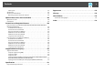
Part Names and Functions 8 The illustrations in this guide are for EB-G6750WU (with the standard zoom lens ELPLS06 attached). Front/Top Name A Air exhaust vent Name B Focus ring Adjusts the image focus. s "Correcting the Focus" p.26 C Zoom ring Adjusts the image size. s "Adjusting the Image Size" p.26 D Lens unit removal button When replacing the lens unit, press this button and then remove the lens unit. s "Removing and Attaching the Projector Lens Unit" p.
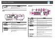
Part Names and Functions Name O Lamp cover 9 Function Open when replacing the projector's lamp. s "Replacing the Lamp" p.128 Interface Rear Name Name Function A Interface s "Interface" p.9 B Security slot The security slot is compatible with the Microsaver Security System manufactured by Kensington. s "Anti-Theft Lock" p.75 C Power inlet Connects to the power cable. D Control panel s "Control Panel" p.
Part Names and Functions Name 10 Function I S-Video port For S-video signals from video sources. J Audio Out port Outputs audio from the currently projected image to an external speaker. K Monitor Out port Outputs to an external monitor the analog signal from the computer connected to the Computer port or the BNC port. You cannot output signals input from other ports or component video signals. L DisplayPort Inputs video signals from DisplayPort compatible computers.
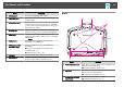
Part Names and Functions Name 11 Function D Security cable installation point Pass a commercially available wire lock through here and lock it in place. s "Installing the wire lock" p.76 E Ceiling mount fixing points (four points) Attach the optional Ceiling Mount here when suspending the projector from a ceiling. s "Installing the Projector" p.20 s "Optional Accessories" p.
Part Names and Functions Name H [Esc] button 12 Function • Stops the current function. • If pressed when the Configuration menu is displayed, it moves to the previous menu level. s "Using the Configuration Menu" p.78 I [ ]/[ ] buttons J [Menu] button • Performs screen adjustments using the settings in Geometric Correction from the Configuration menu. s Settings - Geometric Correctionp.
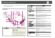
Part Names and Functions Name A [ ] button 13 Function Turns the projector on. B [t] button Turns the projector off. C Change input buttons Changes to images from each input port. s "Switching to the Target Image by Remote Control" p.42 The [HDBaseT] button is only available for EBG6750WU. The [SDI] button is not available for this projector. D [Auto] button If pressed while projecting analog RGB signals from the Computer port or the BNC port, you can automatically optimize Tracking, Sync.
Part Names and Functions Name 14 Function Name Function Q [ID] switch Use this switch to enable (On)/disable (Off) ID settings for the remote control. s "ID Settings" p.28 Y [Color Mode] button Each time the button is pressed, the Color Mode changes. s "Selecting the Projection Quality (Selecting Color Mode)" p.46 R Remote port Connects the optional remote control cable set and outputs signals from the remote control. s "Optional Accessories" p.
Part Names and Functions b Replace the old batteries with new batteries. Remote control operating range Caution Check the positions of the (+) and (-) marks inside the battery holder to ensure the batteries are inserted the correct way. If the batteries are not used correctly, they could explode or leak causing a fire, injury, or damage to the product. c 15 Replace the battery cover. Press the battery compartment cover until it clicks into place.
Part Names and Functions a 16 • To restrict reception of the operation signals from the remote control, set Remote Receiver. s Settings - Remote Receiver p.84 • When using a remote control provided with other Epson projectors, set the Remote Control Type. s Extended - Operation - Remote Control Type p.86 The operating range depends on the remote control that you use.
Part Names and Functions 17 Removing Attention • Only remove the lens unit when necessary. If dust or dirt enter the projector, projection quality deteriorates and it could cause a malfunction. • Try not to touch the lens section with your hand or fingers. If fingerprints or oils are left on the surface of the lens, projection quality deteriorates. • If the lens shift has been done, set the lens shift to the center before replacing the lens unit.
Part Names and Functions c Pull the lens unit straight out as it is released.
Preparing the Projector This chapter explains how to install the projector and connect projection sources.
Installing the Projector Installation Requirements 20 The projector can be installed at the following angles. Vertical: Can be installed at any angle in a complete 360 degrees. The projector can be mounted on a ceiling or placed on a desk. Also, it can be mounted at a tilted angle, so you can flexibly project images to various places. 90 • A special method of installation is required when suspending the projector from a ceiling (ceiling mount).
Installing the Projector 21 Make sure there is a gap of at least 50 cm between the wall and the air exhaust vent and the air intake vent. c Use the [ ][ ] buttons to set the projector's installation angle. d When you have finished making settings, use the [ select Set, and then press the [ ] button. Air exhaust vent Each time you press one of the buttons, the angle of tilt changes by 15 degrees. Set as close to the actual setup angle as possible.
Installing the Projector 22 When Front is the standard, the image directions for each projection mode are as follows. Front (default) Rear a a Press the [Menu] button while projecting. b c d Select Display from Extended. e Press the [Menu] button to finish making settings. s "Using the Configuration Menu" p.78 Front/Ceiling Select Screen Type from Screen. Select the screen's aspect ratio. The shape of the background test pattern changes depending on the setting.
Installing the Projector 23 Adjusting the position of the image on the projected screen You can adjust the position of the image if there are margins between the edge of the image and the projected screen frame due to the Screen Type setting. Example: When the Screen Type is set to 4:3 for EB-G6750WU e Press the [Menu] button to finish making settings. a You can move the image to the left and right. a Press the [Menu] button while projecting. b c d Select Display from Extended.
Installing the Projector b 24 Press the [ ][ ] buttons on the remote control or the [ on the control panel to change the test pattern. Using the remote control Top Menu Name ] button Using the control panel Signal Auto Setup Settings Geometric Correction s p.43 Extended Multi-Projection - Brightness Level - Edge Blending s p.55 - Multi-screen s p.
Installing the Projector 25 a • We recommend setting the focus, zoom, and lens shift at least 30 minutes after you start the projection, because images are not stable right after turning on the projector. • The image will be clearest when both the vertical and horizontal lens shift are set in the center. The ranges within which the image can be moved are shown below. b Turn the vertical and horizontal lens shift dials on the projector to adjust the position of the projected image.
Installing the Projector 26 When using the short throw zoom lens ELPLU01 Follow the steps below to adjust the focus when the lens is shifted up, down, left, or right using the lens shift function. Adjusting the Image Size Turn the zoom ring to adjust the size of the projected image. W a Turn the distortion ring anti-clockwise until it cannot go any further. b Focus the image around the axis of the lens using the focus ring. T Correcting the Focus You can correct the focus using the focus ring.
Installing the Projector 27 d Turn the focus ring to focus the entire screen. If the area around the lens axis is out of focus, fine-tune by turning the distortion ring. a When using the short throw zoom lens ELPLU01, set Lens Type to ELPLU01 from the Configuration menu so that keystone correction is performed correctly. s Extended - Operation - Lens Type p.86 Adjusting the Image Position Extend or retract the front foot to make adjustments.
Installing the Projector 28 Set the projector ID A Extend the rear foot. B Retract the rear foot. a Press the [Menu] button while projecting. b c d Select Multi-Projection from Extended. e Press the [Menu] button to close the configuration menu. s "Using the Configuration Menu" p.78 Select Projector ID, and then press the [ ] button. Select the ID you want to set, and then press the [ ] button. Attention The rear feet can be attached and removed.
Installing the Projector Checking the Projector ID During projection, press the [Help] button while holding the [ID] button. 29 b While holding the [ID] button, press a number button to select a number to match the ID of the projector you want to operate. s "Checking the Projector ID" p.29 Remote control When you press the buttons, the current Projector ID is displayed on the projection screen. It disappears in about three seconds.
Installing the Projector a 30 Submenu • When you turn on the projector for the first time, the message "Do you want to set the time?" is displayed. When you select Yes, the screen from step 4 is displayed. • When Time/Schedule Protection is set to On in Password Protection, settings related to the date and time cannot be changed. You can make changes after setting Time/Schedule Protection to Off. s "Managing Users (Password Protection)" p.72 a Press the [Menu] button while projecting.
Connecting Equipment 31 The port name, location, and connector orientation differ depending on the source being connected. Connecting a Computer To project images from a computer, connect the computer using one of the following methods. A When using the supplied computer cable Connect the computer's display output port to the projector's Computer port.
Connecting Equipment 32 Computer 4 Audio1 BNC Audio2 HDMI HDMI OUT DisplayPort DisplayPort OUT 4 a • Change the audio output from Audio Settings. s Extended - A/V Settings - Audio Settings p.86 • If audio is not sent using an HDMI or DisplayPort cable, connect a commercially available audio cable to the Audio3 port to send the audio. Set HDMI Audio Output or DisplayPort Audio Output to Audio3. s Extended - A/V Settings - Audio Settings - HDMI Audio Output, DisplayPort Audio Output p.
Connecting Equipment 33 Connecting Image Sources To project images from DVD players or VHS video and so on, connect to the projector using one of the following methods. A When using a commercially available video cable Connect the video output port on the image source to the projector's Video port. You can output audio from the projector's speaker by connecting the audio output port on the image source to the projector's Audio-L/R port using a commercially available audio cable.
Connecting Equipment 34 Video Video AUDIO OUT (L,R) Audio-L/R S-Video S-Video 5 AUDIO OUT (L,R) Audio-L/R Computer Y Cb/Pb Cr/Pr AUDIO OUT 4 Audio1 4 Y Cb/Pb Cr/Pr BNC(R/Cr/Pr, G/Y, B/Cb/Pb) AUDIO OUT Audio2 5 HDMI OUT HDMI Attention • If the input source is on when you connect it to the projector, it could cause a malfunction. • If the orientation or shape of the plug differs, do not try to force it in. The device could be damaged or could malfunction.
Connecting Equipment a 35 • Change the audio output from Audio Settings. s Extended - A/V Settings - Audio Settings p.86 • If audio is not sent using an HDMI cable, connect a commercially available audio cable to the Audio3 port to send the audio. Set HDMI Audio Output to Audio3. s Extended - A/V Settings - Audio Settings - HDMI Audio Output p.86 • If the source you want to connect to has an unusually shaped port, use the cable supplied with the device or an optional cable to connect to the projector.
Connecting Equipment a 36 • Make the following settings to output image and audio even when the projector is in standby mode. Set Standby Mode to Communication On. s Extended - Standby Mode p.86 Set A/V Output to Always On. s Extended - A/V Settings - A/V Output p.86 • When the audio cable jack is inserted into the Audio Out port, audio stops being output from the projector's built-in speakers and switches to external output.
Connecting Equipment 37 HDBaseT a • Make sure you read the User's Guide supplied with the HDBaseT transmitter carefully before use. • Use a category 5e or category 6 shielded LAN cable. • When connecting or disconnecting the LAN cable, make sure you turn off the power for the projector and the HDBaseT transmitter. • When performing Ethernet communication or serial communication, or when using the wired remote control via HDBaseT port, set Control Communications to On from the Configuration menu.
Connecting Equipment Installing the Wireless LAN Unit a b 38 c Install the Wireless LAN unit. d Secure the stopper with a screw. e Close the air filter cover. Open the air filter cover. Slide the air filter cover operation knob, and open the air filter cover. Remove the stopper for the Wireless LAN unit.
Connecting Equipment 39 Attaching the Cable Cover By attaching the cable cover, you can hide the connected cables giving a nice, clean finish to the projector installation. (The illustrations are of a projector installed on a ceiling.) Attaching a Bundle the cables together with a commercially available tie. c b Insert the tabs on the cable cover into the two slots on the back of the projector. Tighten the two screws on the cable cover. (You can tighten the screws with your fingers.
Basic Usage This chapter explains how to project and adjust images.
Projecting Images 41 Automatically Detect Input Signals and Change the Projected Image (Source Search) Press the [Search] button on the remote control or the [Source Search] button on the control panel to project images from the port currently receiving an image.
Projecting Images 42 Switching to the Target Image by Remote Control You can change directly to the target image by pressing the following buttons on the remote control. • Press the [Volume] button on the remote control to adjust the volume. [a] Decreases the volume. [b] Increases the volume. Remote control The input ports for each button are shown below. Remote control • Adjust the volume from the Configuration menu. s Settings - Volume p.
Adjusting Projected Images Correcting Distortion in the Projected Image You can correct keystone distortion in projected images using one of the following methods. 43 • Arc Correction Fine adjustment of the curved distortion caused by slack or shrinkage of the screen. s "Arc Correction" p.45 • H/V-Keystone Manually correct distortion in the horizontal and vertical directions independently. s "H/V-Keystone" p.
Adjusting Projected Images c Select H/V-Keystone, and then press the [ d Use the [ 44 ] button. If the message "If this setting is changed, the image may be distorted."is displayed, press the [ ] button. e When you are done, press the [Menu] button to exit the correction menu. Quick Corner ][ ] buttons to select the correction method, and then use the [ ][ ] buttons to make the corrections. This allows you to manually correct each of the four corners of the projected image separately.
Adjusting Projected Images a e If the [Esc] button is pressed for at least 2 seconds, the confirm default reset screen is displayed. Select Yes to reset the result of Quick Corner corrections. Use the [ ], [ the corner. ], [ ], and [ ] buttons to correct the position of When you press the [ ] button, the screen shown in step 4 that allows you to select the area to be corrected is displayed. If the message "Cannot adjust any further.
Adjusting Projected Images 46 Selecting the Projection Quality (Selecting Color Mode) You can easily obtain the optimum image quality simply by selecting the setting that best corresponds to your surroundings when projecting. The brightness of the image varies depending on the mode selected. Mode If the triangle in the direction you are adjusting the shape turns gray, as shown in the screenshot below, you cannot adjust the shape any further in that direction.
Adjusting Projected Images Each time you press the [Color Mode] button, the Color Mode name is displayed on the screen and the Color Mode changes. Remote control 47 • 3D Presentation • 3D Theatre • 3D Multi-Projection a This projector arranges the direction of polarizing projection for R (red), G (green), and B (blue). It is not necessary to inverse left and right eye G (green) image signals. Changing the Aspect Ratio of the Projected Image a You can set Color Mode from the Configuration menu.
Adjusting Projected Images The aspect mode changes as follows. 48 Screen Type: 16:10 Auto or Normal Screen Type: 4:3 Auto or Normal 16:9 4:3 Full 16:9 Zoom Native* Native *Only computer images and images from the HDMI port/HDBaseT port Aspect Mode Screen Type: 16:9 Auto or Normal Full Auto Projects in an appropriate aspect ratio based on information from the signal being input. Normal Projects while retaining the aspect ratio of the input image. 4:3 Projects at an aspect ratio of 4:3.
Adjusting Projected Images a • You can also set the aspect ratio from the Configuration menu. s Signal - Aspect p.82 • If parts of the computer image are missing, set the Resolution setting to Wide or Normal from the Configuration menu, according to the resolution of the computer. s Signal - Resolution p.82 49 s Image - Advanced - Gamma p.81 Select and adjust the correction value s Image - Advanced - Gamma p.
Adjusting Projected Images 50 Move the cursor on the projected image to the part where you want to change the brightness, then press the [ ] button. Use the [ ][ ] buttons to adjust the value. Frame Interpolation (EB-G6750WU/EB-G6650WU/EB-G6550WU/EBG6450WU only) The current and previous frames are used to create intermediate frames, interpolating to produce smooth-moving images. You can resolve clumsymoving images, such as frame skipping when projecting a fast moving image.
Adjusting Projected Images You can select the level of interpolation: Low, Normal or High. Set to Off if noise occurs after setting them.
Useful Functions This chapter explains useful tips for giving presentations, and the Security functions.
Multi-Projection Function When projecting to a wide screen from multiple projectors, you can adjust the difference of brightness and color tone between each projected image to create a seamless screen. There are two general methods of projecting from multiple projectors. U Projecting different images from each projector, and creating a seamless screen 53 Follow the steps below. 1. 2. 3. 4. Set an ID for the projector and the remote control s p.28 Adjust the position of the projected image s p.
Multi-Projection Function 54 Divides the projected image by the grid and corrects the distortion by moving the point of intersection from side to side and up and down. a b c d f Use the [ ], [ ], [ ], and [ ] buttons to move to the point you want to correct, and then press the [ ] button. g Use the [ Press the [Menu] button while projecting. Select Geometric Correction from Settings. Select Point Correction, and then press the [ ] button.
Multi-Projection Function Checking the Color Mode Set the Color Mode to Multi-Projection (or 3D Multi-Projection for 3D images). s p.46 Adjust the Edges of the Images (Edge Blending) When multiple projectors are lined up and projecting images, you can create a seamless screen. Adjusting the brightness of the lamp Before performing edge blending, adjust so that the lamp brightness is the same for each projector. Adjust so that all projectors are the same brightness as the darkest lamp.
Multi-Projection Function 56 d e Turn on Edge Blending. (1) Select Edge Blending, and then press the [ (2) Select On, and then press the [ (3) Press the [Esc] button. Edge Blending Top Edge/Bottom Edge/Right Edge/Left Edge Function Set to On to activate the edge blending function. Set to Off when not projecting from multiple projectors. Blending: Set to On to activate the edge blending function towards where you are setting, and the brend range will be shaded.
Multi-Projection Function (5) (6) (7) 57 In Blend Range, adjust the range to be shaded. The value for when the overlapped range and the guide are in the same position is the best. a b c Press the [Menu] button while projecting. Select Multi-Projection from Extended. Select Multi-screen, and then press the [ ] button. The following screen is displayed. Adjustment Level: There are five levels from white, gray, and up to black. Adjust each level individually. Press the [Esc] button.
Multi-Projection Function g h 58 Return to step 4 and adjust each level. (2) When you are done, press the [Menu] button to exit the correction menu. Select Zoom Display or Full Display, and then press the [ ] button. Zoom Display: Adjusts according to the image currently displayed. Scaling an Image (Scale) A section of the image is cropped and displayed. This allows you to create one large image by combining images projected from multiple projectors.
Multi-Projection Function e 59 Adjust the scale. Select the adjustment method with the [ using the [ ][ ] buttons. ][ ] buttons, then adjust - +: Enlarges or reduces an image horizontally and vertically at the same time. Scale Vertically: Enlarges or reduces an image vertically. Scale Horizontally: Enlarges or reduces an image horizontally. f Adjust the Image Display Range. (1) Select Image Display Range, and then press the [ (2) Use the [ ], [ ], [ ], and [ ] buttons to scroll the image.
Projection Functions Projecting Two Images Simultaneously (Split Screen) You can simultaneously project images from two sources on the right and left of the screen. 60 Operating procedures Projecting on a split screen a Press the [Split] button while projecting. The currently selected input source is projected on the left of the screen. Remote control a a • The following input source combinations cannot be projected using the split screen function.
Projection Functions d 61 Select each input source for Left and Right. b Select Swap Screens, and then press the [ ] button. The projected images on the left and right are swapped. Switching the left and right image sizes a You can perform the same operations using the following procedure. s "Automatically Detect Input Signals and Change the Projected Image (Source Search)" p.41 s "Switching to the Target Image by Remote Control" p.42 e Select Execute, and then press the [ ] button.
Projection Functions 62 The projected images will appear as shown below after setting the screen size. Equal c Select the audio you want to output, and then press the [ button. ] When you select Auto, audio is output for the largest screen. Larger Left If the screens are the same size, audio is output for the screen on the left. Larger Right Ending the split screen Press the [Esc] button to end split screen. The following steps can also be used to end the split screen.
Projection Functions • The user's logo is not displayed. 63 A/V Mute is applied or released each time you press the [A/V Mute] button. Restriction relating to images Remote control • The default values for the Image menu are applied to the image on the right screen. However, the settings for the image projected on the left screen are applied to the image on the right screen for Color Mode, Abs. Color Temp., and Advanced.
Projection Functions 64 Freezing the Image (Freeze) When Freeze is activated on moving images, the frozen image continues to project on the screen, so you can project a moving image one frame at a time like a still photo. Also, you can perform operations such as changing between files during presentations from a computer without projecting any images if the Freeze function is activated beforehand. Each time you press the [Freeze] button, Freeze turns on or off. Remote control a Start E-Zoom.
Projection Functions c 65 Enlarge. a Remote control [z] button: Expands the area each time it is pressed. You can expand quickly by holding the button down. [x] button: Reduces images that have been enlarged. [Esc] button: Cancels E-Zoom. a • During enlarged projection, press the [ [ ], [ ], [ ], or ] buttons to scroll the image. • If User's Logo is selected when Geometric Correction, EZoom or Aspect are being performed, the function currently being performed is temporarily cancelled.
Projection Functions e When you press the [ ] button and the message "Select this image?" is displayed, select Yes. f g Select the zoom factor from the zoom setting screen. When the message "Save this image as the User's Logo?" is displayed, select Yes. The image is saved. After the image has been saved, the message "Completed." is displayed. a When a User's Logo is saved, the previous User's Logo is erased.
Memory Function 67 The settings for the image currently displayed are saved as a memory, allowing you to load them when necessary. Settings for the following menu items are saved in the memory.
Memory Function 68 Function Rename Memory Explanation Changes the memory name. Select the memory name you want to change, and then press the [ ] button. Enter the memory name using the soft keyboard. s "Soft keyboard operations" p.91 When you have finished, move the cursor over Finish, and then press the [ ] button. When a memory has already been saved, the memory name and its color mode are displayed. Function Explanation Load Memory Loads the saved memory.
Scheduling Function 69 You can schedule turning the projector power on/off and switching the input source, as events in the schedule. Registered events are executed automatically at the specified time on the specified dates or weekly. Warning Do not place flammable objects in front of the lens. If you set the schedule to turn on the projector automatically, any flammable objects placed in front of the lens could cause a fire.
Scheduling Function e f 70 Select Save, and then press the [ ] button. To register additional schedules, repeat steps 3 to 5. Select Setup complete, and then select Yes to finish saving. a A calendar is displayed on the Schedule Settings screen (the screen in step 3). The indicator turns on when an event is saved. ( event; : periodic event; : communication on/off; : one-time : event invalid) Use the [ ][ ] buttons to highlight and check the schedule registered for that day.
Scheduling Function a e A repeat icon is displayed for periodic schedules. Perform editing from the menu displayed. Submenu Name f 71 Function On/Off Enable or disable the selected schedule. When a schedule is enabled, the indicator turns green. Edit Edit the content of the selected schedule. Select Save, and then press the [ ] button to complete the editing. Clear Deletes the selected schedule. Add New Save a new schedule. Select Save, and then press the [ ] button to complete the saving.
Security Functions The projector has the following enhanced security functions. • Password Protection You can limit who can use the projector. • Control Panel Lock/Remote Control Button Lock You can prevent people changing the settings on the projector without permission. s "Restricting Operation" p.74 • Anti-Theft Lock The projector is equipped with the following anti-theft security device. s "Anti-Theft Lock" p.
Security Functions a 73 Remote control If Password Protection is already activated, you must enter the password. If the password is entered correctly, the Password Protection setting menu is displayed. s "Entering the Password" p.73 b Select the type of Password Protect you want to set, and then press the [ ] button. (4) Re-enter the password. The message "Password accepted." is displayed. If you enter the password incorrectly, a message is displayed prompting you to re-enter the password.
Security Functions Attention • If an incorrect password is entered three times in succession, the message "The projector's operation will be locked." is displayed for approximately five minutes, and then the projector switches to standby mode. If this happens, disconnect the power plug from the electrical outlet and then reinsert it and turn the projector's power back on. The projector displays the password entry screen again so that you can enter the correct password.
Security Functions a You can release the control panel lock by one of the following two methods. 75 Each time the [Help] button is pressed for at least 5 seconds, the remote control button lock turns on or off. • Use the remote control to set Control Panel Lock to Off from the configuration menu. s Settings - Control Panel Lock p.84 Remote control • Press and hold down the [ ] button on the control panel for about seven seconds, a message is displayed and the lock is released.
Security Functions Installing the wire lock Pass an anti-theft wire lock through the installation point. See the documentation supplied with the wire lock for locking instructions.
Configuration Menu This chapter explains how to use the Configuration menu and its functions.
Using the Configuration Menu This section explains how to use the Configuration menu. Although steps are explained using the remote control as an example, you can perform the same operations from the control panel. Check the guide under the menu for the available buttons and their operations. a b 78 c Select a submenu item. d Change settings. Display the Configuration menu screen. Select a top menu item.
List of Functions 79 Top Menu Name Configuration Menu Table Settable items vary depending on the model being used and the image signal and source being projected. Top Menu Name Image menu s p.81 Signal menu s p.
List of Functions Top Menu Name Info menu s p.
List of Functions Top Menu Name 81 Submenu Name Items or Setting Values IP Address Display On and Off Region Code - Security menu s p.94 Security Open, WPA/WPA2-PSK, WPA/WPA2-EAP Wired LAN menu s p.
List of Functions Submenu 82 Function Tint (Adjustment is possible when a component video signal is being input. If a composite video signal is input, adjustment is only possible when NTSC signals are being input.) You can adjust the image tint. Sharpness Standard: You can adjust the image sharpness. To make moredetailed settings, select Advanced. Advanced: The following four items can be set.
List of Functions 83 Submenu Submenu Function Auto Setup (Only available when an analog RGB computer signal is being input.) Set to On to automatically adjust Tracking, Sync., and Position to the optimum state when the input signal changes. Resolution (Only available when an analog RGB computer signal is being input.) Set to Auto to automatically identify the resolution of the input signal.
List of Functions Submenu 84 Function Input Signal You can select an input signal from the Computer port or BNC port. If set to Auto, the input signal is set automatically according to the connected equipment. If colors do not appear correctly when set to Auto, select the appropriate signal according to the connected equipment. Video Signal You can select an input signal from the Video port or S-Video port. If set to Auto, video signals are recognized automatically.
List of Functions 85 Submenu Function Submenu Function Geometric Correction You can correct distortion. s "Correcting Distortion in the Projected Image" p.43 • H/V-Keystone: Adjust V-Keystone and H-Keystone to correct horizontal and vertical keystone distortion. • Quick Corner: Select and correct the four corners of the projected image. • Arc Correction: Fine adjustment of the curved distortion caused by slack or shrinkage of the screen.
List of Functions Extended Menu 86 Submenu Function Display You can make settings related to the projector's display. Menu Position: Select the position to display the menu on the projected screen. Messages: When set to Off, the following items will not be displayed. Item names when the Source, Color Mode, or Aspect is changed, messages when no signal is being input, and warnings such as High Temp Warning.
List of Functions Submenu 87 Function Projection Select from one of the following projection methods depending on how the projector is installed. Front, Front/Ceiling, Rear, and Rear/Ceiling You can change the setting as follows by pressing down the [A/V Mute] button for about five seconds. FrontWFront/Ceiling RearWRear/Ceiling Direction Set this parameter according to the installation status of the projector. s "Installation Requirements" p.
List of Functions Submenu Function Startup Source Search: Set whether or not (On/Off) to automatically detect the image signal being input when the projector is turned on. A/V Mute Release: (This item cannot be set if User's Logo Protection from Password Protection is set to On. s p.72) When set to A/V Mute, you can only release A/V mute by pressing the [A/V Mute] button (or by sending an A/V mute Off command). When set to Any Button, A/V mute is released when any operation is performed on the projector.
List of Functions 89 Submenu Function HDBaseT (EBG6750WU only) Make settings when the optional HDBaseT Transmitter is connected to the HDBaseT port. Control Communications: When set to On, Ethernet communication from the HDBaseT port, serial communication, and control using the wired remote control connected to the optional HDBaseT Transmitter are all enabled. (When this is enabled, the projector's LAN port, RS-232C port, and Remote port are disabled.
List of Functions 90 s "Setting Password Protection" p.72 Submenu Function Network Configuration The following menus are available for setting Network items. Basic, Wireless LAN, Security, Wired LAN, Administrator Settings, and Reset a By using a Web browser of a computer connected to the projector on a network, you can set functions and control the projector. This function is called Web Control. You can easily enter text using a keyboard to make settings for Web Control such as Security settings.
List of Functions 91 Yes: Saves the settings and exits the Network menu. No: Does not save the settings and exits the Network menu. Cancel: Continues displaying the Network menu. Soft keyboard operations The Network menu contains items that require input of alphanumerics during setup. In this case, the following software keyboard is displayed. Use the [ ][ ][ ][ ] buttons to move the cursor to the desired key, and then press the [ ] button to enter the selected character.
List of Functions Submenu 92 Function Web Remote Password Set a password to use Web Remote. You can enter up to 8 singlebyte alphanumeric characters. (* cannot be used) Web Remote is a computer function that allows you to operate the projector by using the Web browser on a computer connected on a network. s "Changing Settings Using a Web Browser (Web Control)" p.145 Projector Keyword When set to On, you have to enter the keyword when you try to connect the projector to a computer via a network.
List of Functions Submenu Connection Mode 93 Function Set the connection mode to use when connecting the projector and a computer via a wireless LAN. If you select Quick, a small network is created automatically by the projector and computer. It is used with EasyMP Network Projection. If SSID Auto Setting is set to On, the projector becomes an easy access point; if it is set to Off, the network is created in Ad hoc modeg.
List of Functions 94 Search Access Point screen Security menu Detected access points are displayed in a list. Submenu Refresh Function Searches for the access point again. Indicates an already set access point. Indicates the access points where security is set. If you select an access point where security has not been set, the Wireless LAN menu is displayed. If you select an access point where security has been set, the Security menu is displayed.
List of Functions Submenu Security a 95 Function You can select a type of security. • When Quick is selected Open: Security is not set. WPA2-PSK(AES) (only when SSID Auto Setting is set to On): Communication is performed using WPA2 security. Uses AES method for encryption. When establishing a connection from a computer to the projector, enter the value set in the passphrase. • When Advanced is selected Open: Security is not set. WPA2-PSK(AES): Connects in WPA personal mode.
List of Functions 96 When WPA/WPA2-EAP is selected Submenu EAP Method Submenu User name Enter a user name to be used for authentication. You can enter up to 64 single-byte alphanumeric characters. If you select PEAP-TLS or EAP-TLS, the user name obtained automatically from the client certificate is displayed. You can change the user name if the authentication server requires another user name. You can enter up to 32 characters on the Configuration menu.
List of Functions Submenu 97 Function Setting RADIUS Server Name Set to On to perform authentication of the server name during server certificate verification. By specifying the server name, you can reduce the risk of connecting to an invalid authentication server. RADIUS Server Name Specify the authentication server name. You can enter up to 32 single-byte alphanumeric characters. (^ cannot be used.) Verify Exp. date of Server Cert.
List of Functions 98 Administrator Settings menu Submenu Administrator Password Network Host Name PJLink Password Submenu Web Control Password Set a password to use when making settings and controlling the projector using Web Control. You can enter up to 8 single-byte alphanumeric characters. (* cannot be used.) Web Control is a computer function that allows you to set up and control the projector by using the Web browser on a computer connected on a network.
List of Functions Submenu 99 Function Bonjour Set this to On when connecting to the network using Bonjour. See Apple's Web site for more information on the Bonjour service. http://www.apple.com/ EPSON Message Broadcasting You can switch the EPSON Message Broadcasting function to enable or disable. You can download Message Broadcasting and its Operation Guide from the following Web site. http://www.epson.
List of Functions 100 Manage Certificates menu Submenu Function Web Server Certificate (This item can only be set when Secure HTTP is set to On.) The Issued to, Issued by, and Validity period information on the certificate set in the projector is displayed. This information is not displayed when a Self-signed Certificate is set. Select Clear to delete the stored certificate. a Web Control is used to set certificates. s "Setting Certificates" p.
List of Functions Submenu 101 Function Trap IP Address 1/Trap IP Address 2 You can register up to two IP addresses for the SNMP trap notification destination. You can enter a number from 0 to 255 in each field of the address. However, the following IP addresses cannot be used. 127.x.x.x, 224.0.0.0 to 255.255.255.255 (where x is a number from 0 to 255) Community Name Set the community name of SNMP. You can enter up to 32 singlebyte alphanumeric characters. (The only symbol you can use is @.
List of Functions 102 Submenu Info Menu (Display Only) Lets you check the status of the image signals being projected and the status of the projector. Items that can be displayed vary depending on the source currently being projected. Status This is information about errors that have occurred on the projector. This information may be needed if service is required. Serial Number Displays the projector's serial number. Event ID Displays the application error log. s "About Event ID" p.
List of Functions 103 Reset Menu Submenu Function Reset All You can reset all items in the Configuration menu to their default settings. The following items are not reset to their defaults: Input Signal, User's Logo, all items for Network menus, Lamp Hours, Language, Password, Multi-screen, Date & Time, Panel Alignment, and Color Uniformity. Reset Lamp Hours Clears the cumulative lamp hours use time. Reset when you replace the lamp.
Troubleshooting This chapter explains how to identify problems and what to do if a problem is found.
Using the Help 105 If a problem occurs with the projector, the Help screen is displayed to assist you by pressing the Help button. You can solve problems by answering the questions. a c Confirm the selection. Remote control Press the [Help] button. The Help screen is displayed. Remote control Questions and solutions are displayed as shown on the screen below. Press the [Help] button to exit the Help. b Select a menu item.
Problem Solving 106 If you are having a problem with the projector, first check the projector's indicators and refer to "Reading the Indicators" below. See the following if the indicators do not show clearly what the problem might be. s "When the Indicators Provide No Help" p.110 Reading the Indicators The projector is provided with the following four indicators that indicate the operating status of the projector. A Power indicator Indicates the operating status.
Problem Solving 107 Warming up Warm-up time is about 30 seconds. After warm-up is complete, the indicator stops flashing. The [t] button is disabled during warm-up. Projecting B Lamp indicator C Temp indicator D Filter indicator Indicates the projection lamp status. Indicates the internal temperature status. Indicates the air filter status. Refer to the following table to see what the indicators mean and how to remedy problems that they indicate.
Problem Solving Status 108 Cause Remedy or Status When using at an altitude of 1500 m or more, set High Altitude Mode to On. s "Extended Menu" p.86 Lamp Error Lamp Failure Check the following two points. • Take out the lamp and check if it is cracked. s "Replacing the Lamp" p.128 • Clean the air filter. s "Cleaning the Air Filter" p.125 If the lamp is not cracked: Reinstall the lamp and turn on the power. If the error continues: Replace the lamp with a new one and then turn on the power.
Problem Solving Status 109 Cause High Temp Warning Remedy or Status (This is not an abnormality. However, if the temperature rises too high again, projection stops automatically.) • Check that the air filter and air exhaust vent are clear, and that the projector is not positioned against a wall. • If the air filter is clogged, clean or replace it. s "Cleaning the Air Filter" p.125 s "Replacing the Air Filter" p.131 Replace Lamp Replace it with a new lamp. s "Replacing the Lamp" p.
Problem Solving 110 When the Indicators Provide No Help If any of the following problems occur and the indicators do not offer a solution, refer to the pages given for each problem. Problems Relating to Images sp.111 • No images appear Projection does not start, the projection area is completely black, or the projection area is completely blue. • Moving images are not displayed Videos played back on a computer are black or no image is projected, or the video is not played back on the computer. sp.
Problem Solving 111 Problems Relating to Images No images appear Check Remedy ] button on the remote control or the [t] Did you press the [ button on the control panel? Press the [ ] button on the remote control or the [t] button on the control panel to turn on the projector. Are the indicators switched off? The power cord is not connected correctly or power is not being supplied. Connect the projector's power cord correctly.
Problem Solving 112 Check Are the contents of the moving image you are trying to project copyright protected? Remedy The projector may not be able to project copyright protected moving images that are being played back on a computer. For more details, see the user's guide supplied with the player. Projection stops automatically Check Is Sleep Mode set to On? Remedy ] button on the remote control or the [t] button on the control panel to turn on the projector.
Problem Solving 113 Check Are the image signals being output to the projector? (Only when projecting images from a laptop computer or a computer with a built-in LCD screen) Remedy If the image signals are only being output to the computer's LCD monitor or to the accessory monitor, you need to change the output to an external destination as well as the computer's own monitor.
Problem Solving 114 Check Remedy Are the cables connected correctly? Check that all the cables required for projection are securely connected. s "Connecting Equipment" p.31 Is an extension cable being used? If an extension cable is used, electrical interference may affect the signals. Use the cables supplied with the projector to check if the cables you are using may be causing the problem.
Problem Solving 115 Check Is the image position adjusted correctly? Remedy (Only when projecting analog RGB signals input from the Computer port) Press the [Auto] button on the remote control or the [ ] button on the control panel to adjust the position. You can also adjust the position from the Configuration menu. s Signal - Position p.
Problem Solving 116 Check Remedy Is the color adjustment set correctly? Adjust the Gamma, RGB, or RGBCMY setting from the Configuration menu. s Image - Advanced p.81 s "Adjusting the Image" p.49 Are the color saturation and tint adjusted correctly? (Only when projecting images from a video source) Adjust the Color Saturation and Tint settings from the Configuration menu. s Image - Color Saturation, Tint p.
Problem Solving 117 Check Are the indicators switched off? Remedy The power cord is not connected correctly or power is not being supplied. Disconnect and then reconnect the power cord. Check that your electrical outlet or power source is functioning correctly. Do the indicators turn on and off when the power cord is touched? There is probably a poor contact in the power cable, or the power cable may be defective. Reinsert the power cable.
Problem Solving 118 Check Is the projector volume set to the minimum? Remedy Adjust the volume so that sound can be heard. s Settings - Volumep.84 s "Adjusting the Volume" p.42 Is the volume for the computer or from the image source set to the Adjust the volume so that sound can be heard. minimum? Is A/V Mute active? Press the [A/V Mute] button to release A/V Mute. s "Hiding the Image and Sound Temporarily (A/V Mute)" p.
Problem Solving 119 Check Remedy Does Remote Control Type match the remote control that you are Check the Remote Control Type on the configuration menu. using? s Extended - Operation - Remote Control Type p.86 Is the optional remote control cable connected to the projector's Remote port? When the remote control cable is connected, the projector's remote receiver is disabled. When not using the remote control cable set, disconnect it from the Remote port.
Problem Solving 120 The authentication setting of wireless LAN fails Check Is the time set correctly? Remedy If the wireless LAN is set correctly but the authentication setting fails, the time may not be set correctly. Check if it is set correctly. s "Setting the Time" p.
Problem Solving 121 Cannot change settings using a Web browser Check Are the user ID and password correct? Remedy Enter "EPSONWEB" as the user ID. This cannot be changed. Enter the user ID even if the password setting is disabled. Enter the characters set for the Web Control Password as the password. The default password is "admin".
About Event ID 122 Check the numbers and then apply the following countermeasures. If you cannot resolve the problem, contact your network administrator, or contact your local dealer or the nearest address provided in the Epson Projector Contact List. s Epson Projector Contact List Event ID Cause Remedy 0432 0435 Failed to startup EasyMP Network Projection. Restart the projector. 0434 0481 0482 0485 Network communication is unstable.
About Event ID 123 Event ID 089D Cause Key exchange failed.
Maintenance This chapter provides information on maintenance procedures to ensure the best level of performance from the projector for a long time to come.
Cleaning You should clean the projector if it becomes dirty or if the quality of projected images starts to deteriorate. Caution When cleaning, unplug the power cable from the electric outlet. Otherwise, it could cause an electric shock. Cleaning the Projector's Surface Clean the projector's surface by wiping it gently with a soft cloth.
Cleaning b c Open the air filter cover. Slide the air filter cover operation knob, and open the air filter cover. 126 d With the front (the side with tabs) of the air filter facing down, tap the air filter four or five times to shake off the dust. Turn it over and tap the other side in the same way. Remove the air filter. Attention Grip the tab in the center of the air filter, and pull it straight out. If the air filter is hit too hard, it may become unusable due to deformities and cracks.
Cleaning 127 f Replace the air filter. g Close the air filter cover. Press until it clicks into place. a • If a message is frequently displayed, even after cleaning, it is time to replace the air filter. Replace it with a new air filter. s "Replacing the Air Filter" p.131 • It is recommended that you clean these parts at least once every three months. Clean them more often than this if using the projector in a particularly dusty environment.
Replacing Consumables This section explains how to replace the lamp and the air filter. Replacing the Lamp Lamp replacement period It is time to replace the lamp when: • The following message is displayed. "It is time to replace your lamp. Please contact your Epson projector reseller or visit www.epson.com to purchase." 128 Attention • The lamp replacement message is set to appear after the following time periods in order to maintain the initial brightness and quality of the projected images.
Replacing Consumables a • We recommend that you clean the air filter whenever you replace the lamp. s "Cleaning the Air Filter" p.125 129 b Wait until the lamp has cooled down, then remove the projector's lamp cover. Loosen the Lamp cover fixing screw with the screwdriver supplied with the new lamp unit or a cross-head screwdriver, and then remove the lamp cover.
Replacing Consumables d Take out the old Lamp by pulling the handle. If the Lamp is cracked, replace it with a new lamp, or contact your local dealer for further advice. 130 f Tighten the two lamp fixing screws. g Replace the lamp cover. s Epson Projector Contact List e Install the new lamp. Insert the lamp along the guide rail in the correct direction so that it fits in place and press it firmly to the back.
Replacing Consumables Attention • Make sure you install the lamp securely. If the lamp cover is removed, the power turns off automatically as a safety precaution. If the lamp or the lamp cover is not installed correctly, the power does not turn on. • This product includes a lamp component that contains mercury (Hg). Please consult your local regulations regarding disposal or recycling. Do not dispose of it with normal waste.
Replacing Consumables 132 a d Install the new air filter. e Close the air filter cover. Press until it clicks into place. Dispose of used air filters properly in accordance with your local regulations.
Notes on Transportation There are many glass parts and precision components inside the projector. To prevent damage due to impacts when transporting, handle the projector as follows. 133 • Fit the protective lens pad that was used at the time of purchase. Notes when packing and transporting Moving Nearby Check the following points, and move the projector carefully. • Turn off the power to the projector and disconnect all cables. • Attach the cover to the lens.
Image Maintenance 134 Panel Alignment Adjusts the pixel color shift for the LCD panel. You can adjust the pixels horizontally and vertically by 0.25 pixels within a range of ±1 pixel. a a b c • Image quality may decline after performing LCD alignment. • Images for pixels that extend beyond the edge of the projected screen are not displayed. Press the [Menu] button while projecting. Select Display from Extended. Select Panel Alignment, and then press the [ ] button.
Image Maintenance (2) (3) g 135 Select a combination of R (red), G (green), and B (blue) for the grid color. R/G/B: Displays a combination all three colors; red, green and blue. The actual color of the grid is white. R/G: This is available when R is selected from Select Color. Displays a combination of two colors; red and green. The actual color of the grid is yellow. G/B: This is available when B is selected from Select Color. Displays a combination of two colors; green and blue.
Image Maintenance 136 h Use the [ ], [ ], [ ], and [ ] buttons to select the area you want to adjust, and then press the [ ] button. If you select the center, the whole screen is adjusted. Adjust the outer areas first, and then adjust the whole screen. Adjustment Level: There are five levels from white, through gray, and up to black. You can adjust each level individually. Start Adjustments: Starts making color uniformity adjustments.
Image Maintenance k 137 When you are done, press the [Menu] button. Adjusting the Lens Balance The lens may tilt depending on the projector's installation angle or the weight of the lens unit that is attached. If the lens is tilted, images may be out of focus. Adjust the lens balance if some areas of the projected image are out of focus. Special techniques are necessary to adjust the lens balance. Contact your local dealer or the nearest address provided in the Epson Projector Contact List.
Image Maintenance 138 a Attention Keep the screws in a safe place as you will need these when transporting the projector. f Use the following pattern to adjust the lens balance. Loosen the locking screws (three points) by 1/4 of a turn (45˚) with a ball point hexagonal wrench. j Adjust the focus with the focus ring. s "Correcting the Focus" p.26 Check the areas that are out of focus on the projection screen. 45 k l Press the [A/V Mute] button to temporarily hide the images.
Image Maintenance 139 n Press the [Test Pattern] button on the remote control or the [ button on the control panel to display the test pattern. o Adjust the lens balance by turning the adjustment screws with the ball point hexagonal wrench. ] A Loosen B Tighten When the screws are loosened the focus moves to the rear, and when the screws are tightened the focus is brought to the front.
Image Maintenance s See step 4 to attach the inner cap, and then see step 3 to attach the cover. t Attach the projector lens unit. Attention When performing the following operations, attach the fixing screws, and then tighten all screws to their initial positions. • When transporting • When readjusting the lens balance If the screws are not tightened to their initial positions, a malfunction could occur.
Appendix
Network Functions This chapter explains the additional functions for networks. Projecting with "Connect to a Network Projector" The projector supports the Windows "Connect to a Network Projector" function. For more information about the "Connect to a Network Projector" function, see the documentation supplied with your computer or the Microsoft's Web site. a • Make sure the computer and projector are ready to connect to the network.
Network Functions 143 • The wireless LAN unit (ELPAP07) is connected to the projector. • The projector is setup to connect to the network using wireless LAN. s "Wireless LAN menu" p.92 a Turn on the projector, and then press the [LAN] button on the remote control. The following screen is displayed. The following screen is displayed. b Check that the SSID and IP address information are displayed, and then remove the wireless LAN unit. s "Installing the Wireless LAN Unit" p.
Network Functions d When the message "Network information update complete. Remove the Quick Wireless Connection USB Key Adapter." is displayed, remove the Quick Wireless Connection USB Key. After removing the Quick Wireless Connection USB Key, reattach the wireless LAN unit. e Connect the Quick Wireless Connection USB Key to the computer. From this point on, see the user's guide supplied with the Quick Wireless Connection USB Key.
Monitoring and Controlling About EasyMP Monitor EasyMP Monitor lets you carry out operations such as checking the status of multiple Epson projectors that are connected to a network at a computer monitor, and controlling the projectors from the computer. 145 a If you set Standby Mode to Communication On, you can use the Web browser to make settings and perform control even if the projector is in standby mode (when the power is off). s Extended - Standby Mode p.
Monitoring and Controlling a a b If your Web browser is set up to connect via a proxy server, the Web Control screen cannot be displayed. To display Web Control, you need to make settings so that a proxy server is not used for a connection. Start the Web browser on the computer. Enter the IP address of the projector in the address input box of the Web browser, and press the Enter key on the computer's keyboard. The Web Control screen is displayed. 146 a Display Web Control.
Monitoring and Controlling a 147 When installing a certificate, make sure the projector supports its format. Item Password Explanation Required. Up to 32 alphanumeric characters s "List of supported certificates" p.147 Server Certificate (PEAP/PEAP-TLS/EAP-TLS/EAP-Fast) Item Secure HTTP Notes When Secure HTTP in Administrator Settings from the Network menu is set to On, security using HTTPS protocol is automatically applied.
Monitoring and Controlling Using the Mail Notification Function to Report Problems When you set Mail Notification, notification messages are sent to the preset email addresses when a problem or warning occurs with a projector. This will enable the operator to be notified of problems with projectors even at locations away from the projectors. s Network - Administrator Settings - Mail Notification p.98 a 148 The details of the problem are listed line by line. The main message contents are listed below.
Monitoring and Controlling 149 Management Using SNMP By setting SNMP to On in the Configuration menu, notification messages are sent to the specified computer when a problem or warning occurs. This will enable the operator to be notified of problems with projectors even at locations away from the projectors. s Network - Administrator Settings - SNMP p.98 a • SNMP should be managed by a network administrator or someone who is familiar with the network.
Monitoring and Controlling 150 Item ESC/VP21 Commands A/V Mute On/Off You can control the projector from an external device using ESC/VP21. When the power ON command is transmitted to the projector, the power turns on and it enters warm-up mode. When the projector's power has turned on, a colon ":" (3Ah) is returned. When a command is input, the projector executes the command and returns a ":", and then accepts the next command.
Monitoring and Controlling 151 • Projector input port name: RS-232C About PJLink PJLink Class1 was established by the JBMIA (Japan Business Machine and Information System Industries Association) as a standard protocol for controlling network-compatible projector's as part of their efforts to standardize projector control protocols. The projector complies with the PJLink Class1 standard established by the JBMIA.
Monitoring and Controlling 152 Source • Remote operation using a Web browser You can operate a projector from your computer just like using a remote control.
Monitoring and Controlling a b 153 Start the Web browser on the computer. Enter the IP address of the projector in the address field of the Web browser, and press the Enter key on the keyboard. Button Function Turns the video and audio on or off. s "Hiding the Image and Sound Temporarily (A/V Mute)" p.63 A/V Mute The operation window is displayed. B Switch to the image from the selected input source. To display input sources that are not shown in Source List, click (a) or (b) to scroll up or down.
Monitoring and Controlling Button 154 Function OK Performs the same operation as the [ remote control. s "Remote Control" p.12 Menu Displays and closes the Configuration menu. Auto If clicked while projecting analog RGB signals from the Computer port, you can automatically optimize Tracking, Sync., and Position. Search Changes to the next input source that is sending an image. s "Automatically Detect Input Signals and Change the Projected Image (Source Search)" p.
Monitoring and Controlling Item 155 Function DHCP Select the Enabled check box to use DHCP. You cannot enter an IP address if DHCP is enabled. IP Address Enter the IP address to assign to the currently connected projector. Subnet Mask Enter a subnet mask for the currently connected projector. Default Gateway Enter the gateway address for the currently connected projector. Send Click this button to confirm the changes made to the Projector.
Optional Accessories and Consumables The following optional accessories and consumables are available. Please purchase these products as and when needed. The following list of optional accessories and consumables is current as of: January 2013. Details of accessories are subject to change without notice and availability may vary depending on the country of purchase. 156 Remote control cable set ELPKC28 (10 m 2 piece set) Use this to guarantee operation from the remote control from a distance.
Optional Accessories and Consumables Consumables Lamp unit ELPLP76 Use as a replacement for used lamps. Air filter ELPAF43 Use as a replacement for used air filters.
Screen Size and Projection Distance Projection Distance (For EB-G6750WU/EBG6650WU/EB-G6550WU/EB-G6450WU/EBG6250W/EB-G6050W) 158 Unit: cm 4:3 Screen Size A B Minimum (Wide) to Maximum (Tele) Vertical Lens Shift Top to Bottom 50" 102x76 154 - 280 -13 - +90 60" 122x91 185 - 337 -16 - +108 70" 142x107 217 - 393 -19 - +126 80" 163x122 249 - 450 -22 - +143 100" 203x152 312 - 564 -27 - +179 150" 305x229 471 - 848 -40 - +269 200" 406x305 630 - 1132 -54 - +359 250" 508x381 788 -
Screen Size and Projection Distance 159 Unit: cm A 16:10 Screen Size Unit: cm B Minimum (Wide) to Maximum (Tele) Vertical Lens Shift Top to Bottom 16:9 Screen Size A B Minimum (Wide) to Maximum (Tele) Vertical Lens Shift Top to Bottom 50" 108x67 135 - 247 -12 - +79 60" 133x75 84 - 101 -19 - +94 60" 130x81 163 - 297 -14 - +95 80" 177x100 113 - 136 -25 - +125 80" 172x108 219 - 397 -19 - +127 100" 221x125 143 - 171 -31 - +156 100" 215x135 275 - 498 -24 - +158 150" 332x1
Screen Size and Projection Distance 160 Unit: cm 4:3 Screen Size A B 50" 102x76 91 +38 60" 122x91 110 +46 70" 142x107 129 +53 80" 163x122 148 +61 100" 203x152 186 +76 150" 305x229 280 +114 Unit: cm 4:3 Screen Size Unit: cm 16:9 Screen Size A B 50" 111x62 82 +31 60" 133x75 99 +37 80" 177x100 134 +50 100" 221x125 168 +62 150" 332x187 254 +93 A B 50" 108x67 80 +34 60" 130x81 96 +40 80" 172x108 130 +54 100" 215x135 163 +67 150" 323x202 247
Screen Size and Projection Distance 161 Unit: cm A 16:10 Screen Size Unit: cm B Minimum (Wide) to Maximum (Tele) Vertical Lens Shift Top to Bottom 16:9 Screen Size A B Minimum (Wide) to Maximum (Tele) Vertical Lens Shift Top to Bottom 50" 108x67 242 - 371 -12 - +79 50" 111x62 371 - 571 -16 - +78 60" 130x81 292 - 447 -14 - +95 60" 133x75 449 - 689 -19 - +94 80" 172x108 392 - 599 -19 - +127 80" 177x100 604 - 924 -25 - +125 100" 215x135 493 - 751 -24 - +158 100" 221x125
Screen Size and Projection Distance 162 Unit: cm Long throw zoom lens ELPLL06 Unit: cm 4:3 Screen Size A B Minimum (Wide) to Maximum (Tele) Vertical Lens Shift Top to Bottom 50" A B Minimum (Wide) to Maximum (Tele) Vertical Lens Shift Top to Bottom 108x67 546 - 742 -12 - +79 16:10 Screen Size 50" 102x76 620 - 842 -13 - +90 60" 130x81 659 - 894 -14 - +95 60" 122x91 748 - 1015 -16 - +108 80" 172x108 884 - 1198 -19 - +127 70" 142x107 876 - 1187 -19 - +126 100" 215x135 111
Screen Size and Projection Distance 163 Unit: cm Projection Distance (For EB-G6350/EB-G6150) 4:3 Screen Size A B Minimum (Wide) to Maximum (Tele) Vertical Lens Shift Top to Bottom 30" 61x46 76 - 141 -3 - +49 40" 81x61 103 - 189 -5 - +66 50" 102x76 130 - 238 -6 - +82 60" 122x91 157 - 286 -7 - +98 80" 163x122 211 - 383 -9 - +131 100" 203x152 265 - 479 -12 - +164 150" 305x229 400 - 721 -17 - +246 200" 406x305 535 - 963 -23 - +328 250" 508x381 670 - 1205 -29 - +410 30
Screen Size and Projection Distance A 16:9 Screen Size 164 B Minimum (Wide) to Maximum (Tele) Vertical Lens Shift Top to Bottom 4:3 Screen Size A B Minimum (Wide) to Maximum (Tele) Vertical Lens Shift Top to Bottom 250" 553x311 730 - 1313 -83 - +395 80" 163x122 105 - 127 -9 - +131 275" 609x342 803 - 1445 -92 - +434 100" 203x152 133 - 160 -12 - +164 150" 305x229 201 - 242 -17 - +246 200" 406x305 270 - 324 -23 - +328 Unit: cm 16:10 Screen Size A B 250" 508x381 338 - 407
Screen Size and Projection Distance 16:10 Screen Size 165 A B Minimum (Wide) to Maximum (Tele) Vertical Lens Shift Top to Bottom 16:9 Screen Size 100" 215x135 141 - 170 -26 - +160 150" 323x202 214 - 257 -39 - +241 200" 431x269 286 - 344 -51 - +321 250" 538x337 359 - 431 -64 - +401 283" 610x381 407 - 489 -73 - +454 A B 50" 111x62 83 +31 60" 133x75 101 +37 80" 177x100 136 +50 100" 221x125 171 +62 150" 332x187 259 +93 184" 407x229 318 +114 Unit: cm Rear pr
Screen Size and Projection Distance 4:3 Screen Size 166 Unit: cm A B Minimum (Wide) to Maximum (Tele) Vertical Lens Shift Top to Bottom 16:10 Screen Size A B Minimum (Wide) to Maximum (Tele) Vertical Lens Shift Top to Bottom 80" 163x122 378 - 577 -9 - +131 100" 203x152 475 - 723 -12 - +164 38" 82x51 184 - 284 -10 - +61 150" 305x229 717 - 1090 -17 - +246 50" 108x67 247 - 379 -13 - +80 200" 406x305 959 - 1456 -23 - +328 60" 130x81 298 - 456 -15 - +96 250" 508x381 120
Screen Size and Projection Distance A 4:3 Screen Size 300" 610x457 167 B Minimum (Wide) to Maximum (Tele) Vertical Lens Shift Top to Bottom 2162 - 3289 -35 - +492 Unit: cm 16:9 Screen Size A B Minimum (Wide) to Maximum (Tele) Vertical Lens Shift Top to Bottom 100" 215x135 753 - 1152 -26 - +160 150" 323x202 1138 - 1736 -39 - +241 200" 431x269 1523 - 2320 -51 - +321 A B 250" 538x337 1908 - 2904 -64 - +401 Minimum (Wide) to Maximum (Tele) Vertical Lens Shift Top to Bottom 283"
Screen Size and Projection Distance 168 Unit: cm 16:9 Screen Size A B Minimum (Wide) to Maximum (Tele) Vertical Lens Shift Top to Bottom 16:10 Screen Size 37" 82x46 416 - 568 -12 - +58 40" 89x50 455 - 620 -13 - +63 50" 111x62 574 - 780 -17 - +79 60" 133x75 692 - 939 -20 - +95 80" 177x100 929 - 1259 -27 - +126 100" 221x125 1166 - 1578 -33 - +158 150" 332x187 1758 - 2376 -50 - +237 200" 443x249 2350 - 3174 -67 - +316 250" 553x311 2942 - 3972 -83 - +395 275" 609x342
Supported Monitor Displays 169 Supported Resolutions Computer signals (analog RGB) Signal Refresh Rate (Hz) Resolution (Dots) MAC21" 75 1152x870 *1 Only compatible when Wide is selected as the Resolution from the Configuration menu. (This is not available for EB-G6350/EB-G6150.) *2 EB-G6750WU/EB-G6650WU/EB-G6550WU/EB-G6450WU only. Only compatible when VESA CVT-RB (Reduced Blanking) signal is input.
Supported Monitor Displays 170 Input signal from the HDMI port and DisplayPort (EB-G6750WU/ EB-G6650WU/EB-G6550WU/EB-G6450WU/EB-G6250W/EB-G6050W) Input signal from the HDMI port and DisplayPort (EB-G6350/EBG6150) Signal Refresh Rate (Hz) Resolution (Dots) Signal Refresh Rate (Hz) Resolution (Dots) VGA 60 640x480 VGA 60 640x480 SVGA 60 800x600 SVGA 60 800x600 XGA 60 1024x768 XGA 60 1024x768 WXGA 60 1280x800 WXGA 60 1280x800 60 1280x768*1 60 1280x768*1 60 1366x768 60 1
Specifications 171 Projector General Specifications Product name EB-G6750WU EB-G6650WU EB-G6450WU 0.76" Wide 2,304,000 pixels WUXGA (1920 (W) x 1200 (H) dots) x 3 EB-G6050W 0.76" Wide 0.79" 0.76" Wide 786,432 pixels XGA (1024 (W) x 768 (H) dots) x 3 1,024,000 pixels WXGA (1280 (W) x 800 (H) dots) x 3 786,432 pixels XGA (1024 (W) x 768 (H) dots) x 3 1,024,000 pixels WXGA (1280 (W) x 800 (H) dots) x 3 Manual (Vertical direction: Maxi‐ mum approx. 67%, Horizontal direction: Maxi‐ mum approx.
Specifications Power consumption 172 100 to 120 V area Operating: 498 Operating: 528 Operating: 568 W Operating: 468 Operating: 528 Operating: 568 W W W W W Standby power consumption (Com‐ Standby power consumption (Com‐ Standby power Standby power munication On): 2.8 W Standby power Standby power munication On): 2.
Specifications Connectors 173 Computer Port 1 Mini D-Sub15-pin (female) blue Audio1 port 1 Stereo mini jack (3.5Ф) BNC port 1 5BNC (female) Audio2 port 1 Stereo mini jack (3.5Ф) DisplayPort 1 DisplayPort HDMI port 1 HDMI HDCP supported (Audio is only supported by PCM) Audio3 port 1 Stereo mini jack (3.5Ф) S-Video port 1 Mini DIN 4-pin Video port 1 RCA pin jack Audio-L/R port 1 RCA pin jack x 2 (L-R) Audio Out port 1 Stereo mini jack (3.
Specifications 174 DECLARATION of CONFORMITY According to 47CFR, Part 2 and 15 Class B Personal Computers and Peripherals; and/or CPU Boards and Power Supplies used with Class B Personal Computers We: Located at: Tel: Epson America, Inc. 3840 Kilroy Airport Way MS: 3-13 Long Beach, CA 90806 562-981-3840 Declare under sole responsibility that the product identified herein, complies with 47CFR Part 2 and 15 of the FCC rules as a Class B digital device.
Appearance 175 84.6 149 Units: mm 252.5 18.6 505 Center of lens Distance from center of lens to suspension bracket fixing point 149.4 A B 405.5 180 256.
Glossary 176 This section briefly explains the difficult terms that are not explained in the text of this guide. For details, refer to other commercially available publications. Ad hoc mode A method of wireless LAN connection that communicates with wireless LAN clients without using an access point. AMX Device Discovery AMX Device Discovery is a technology developed by AMX to facilitate AMX control systems for easy operation of the target equipment.
Glossary 177 IP Address A number to identify a computer connected to a network. Progressive Projects information to create one screen at a time, displaying the image for one frame. Even though the number of scan lines is the same, the amount of flicker in images decreases because the volume of information has doubled compared with an interlace system. Refresh Rate The light-emitting element of a display maintains the same luminosity and color for an extremely short time.
General Notes All rights reserved. No part of this publication may be reproduced, stored in a retrieval system, or transmitted in any form or by any means, electronic, mechanical, photocopying, recording, or otherwise, without the prior written permission of Seiko Epson Corporation. No patent liability is assumed with respect to the use of the information contained herein. Neither is any liability assumed for damages resulting from the use of the information contained herein.
Index 3 179 C 3D Setup ........................................................ 83 CA certificate .............................................. 100 Ceiling ........................................................... 87 Ceiling mount fixing points ....................... 11 Certificates .................................................. 146 Cleaning ...................................................... 125 Cleaning the air filter and air intake vent ......................................................
Index 180 Horizontal lens shift dial .............................. 8 How to replace the air filter ..................... 131 How to replace the lamp ........................... 129 Messages ....................................................... 86 Monitor displays ........................................ 169 Monitor Out port ......................................... 10 Monitor Password ....................................... 98 Mosquito NR ................................................
Index 181 Resetting the lamp operating time ................................................................ 103, 131 Resolution ............................................. 83, 102 RoomView .................................................. 152 RS-232C port .................................................. 9 sRGB .............................................................. 46 Standby Mode .............................................. 88 Startup Screen ..............................................