
Specifications


EPL-5700 Chapter4 Disassembly and Assembly
Rev. A
4-2
7
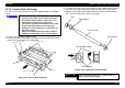
4.2.21 Paper Sensor(PS1) Removal
1. Remove the right cover.(See section 4.2.2)
2. Remove the paper empty sensor. (See section 4.2.4)
3. Remove the control panel. (See section 4.2.6)
4. Remove the front cover. (See section 4.2.7)
5. Remove the shield cover of the main control board. (See section 4.2.9)
6. Remove the left cover.(See section 4.2.10)
7. Remove the top cover. (See section 4.2.14)
8. Remove the rear cover. (See section 4.2.15)
9. Remove the power unit. (See section 4.2.19)
10. Release the hook of sensor securing the paper feed sensor to the paper
guide, and remove the sensor.
11. Remove the harness of the sensor from the connector of the paper feed
sensor.
Paper Feed Sensor
Hook
Paper Feed
Sensor
Sensor Harness
Figure 4-36. Paper Feed Sensor Removal
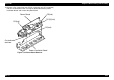
4.2.22 Main Motor Removal
1. Remove the right cover. (See section .4. 2.2)
2. Remove the paper empty sensor. (See section 4.2.4)
3. Remove the control panel. (See section 4.2.6)
4. Remove the front cover. (See section 4.2.7)
5. Remove the shield cover of the main control board. (See section 4.2.9)
6. Remove the left cover.(See section 4.2.10)
7. Remove the top cover. (See section 4.2.14)
8. Remove the rear cover. (See section 4.2.15)
9. Remove the power unit. (See section 4.2.19)
10. Remove the main motor harness from connector CN206 on the main
control board.
11. Remove the main motor harness from the clamp part of the paper guide.
12. Remove two CP(O) screws securing the main motor to the left frame.
13. Remove the main motor from the printer inside.
CP(O)(3x8)
CP(O)(3x8)
Main Motor
Motor Harness
Left Frame
Clamp Parts
(4 positions)
Figure 4-37. Main Motor Removal