
Specifications


EPL-5700 Chapter3 Troubleshooting
Rev. A
3-1
3.1 OVERVIEW
Like other page printers, there are many error modes in this printer, making
identification of failed parts or component more difficult. In order to solve this
problem, this chapter shows how to check and identity malfunction from the
major components, and how to identify the causes from the errors or
abnormal symptom.
3.2 ELECTRIC CHECK POINT
CAUTION
Use the recommended fuses.
Avoid checking the IC terminal directly by the
tester. Check the connector on the board to
judge if it is not defective or not.
3.2.1 Rating of Power Fuse F1
Table below shows rated power fuse F1.
Table 3-1. Rated Power Fuse
Power Voltage F1
100V type 8A 125V
200V type 4A 250V
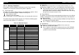
3.2.2 Coil Resistance of Main Motor
By measuring the coil resistance of the main motor, the motor can be
checked if it is working all right or not. Following table shows how to
measure the coil resistance.
Table 3-2. Coil Resistance of the Motor
Motor Measuring
Point
Measuring Value of coil
resistance
Main Motor Pin1 and
Pin2, or Pin3
and Pin4.
Set the multi-meter to
the resistance measuring
range. Connect the one
lead to one pin, and
connect the other side of
lead to the another pin
then measure the coil
resistance.
2.4 Ω ± 10%
(25 °C)
Pin1
Pin4
Pin3
Pin4
Pin1 Pin2
M
Figure 3-1. Motor Connection