
Specifications


EPL-5700 Chapter2 Operating Principles
Rev. A
2-1
4
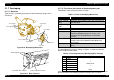
2.2 ELECTRIC CIRCUIT
Electric circuit of this printer consists of main control circuit, power supply
unit, high voltage board, laser diode control board(in the print head unit).
Following shows location of electric circuit, sensors and motors. Table2-6
shows function of each circuit and board.
Paper Feed Sensor
Paper Eject Sensor
Thermister
Thermostat
Heater Lamp
Power Unit
Main Motor
Power Switch
High Voltage Board
Control Panel Board
Main Control Board
Inter Lock Switch
Paper Feed Solenoid
Paper Empty Sensor
Laser Diode Control Board
Figure 2-17. Locations of Electric Parts in the Printer
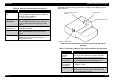
Table 2-5. Function of Each Electric Parts
Name Function
Heater lamp Heats up the heat roller.
High voltage board Provides following voltages to each
following unit.
• Rotation charge brush: Charging
voltage
• Sleeve roller: Developing bias voltage.
• Toner regulation board: Developing
blade voltage.
• Toner collecting board: Collecting blade
voltage.
• Transfer roller: Transfer voltage.
Main motor Driving power source for the printer.
Paper empty sensor(PE1) Detects if there is any paper or not.
• Paper in: Low
Paper Feed sensor(PS1)
• Detects the paper is fed.
• In order to judge the paper size, PS1
detects the paper length. But paper
width can not be detected.
•Paper in: Low
Paper eject sensor (PS3) Detects the paper is ejected to judge the
paper jam.
Power unit
• Provides power supply voltage to each
circuit in the printer, generating dc
voltage from ac power.
• AC power is supplied to the heater
lamp.
Main control board This board has video controller part and
engine controller. This board
communicates with host computer through
the interface, and controls all operations.
Operation panel board Switches to operate the printer are
mounted on this board.