
Specifications


EPL-5700 Chapter7 Appendix
Rev. A
7-1
7.1 CONECTOR PIN ASSIGMENTS
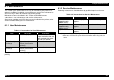
Figure below shows interconnections with main board.
SIMM
CN5
CN6
RS-422
CN7
CN9
CN202
CN203
CN204
CN205
CN206
CN207
CN208
CN209
CN210
CN211
CN212
CN1
CN2
CN3
C234 Main-B Board
Heater
Lamp
Interlock
Switch
Power Board
2nd
Paper
Feed Unit
Parallel
I/F
Control
Panel
Fusin
g
Thermister
Paper Feed
Solenoid
High Voltage
Board
Print Head
Main
Motor
Paper Eject
Sensor
Polygon
Motor
Paper Feed
Sensor
Paper Empty
Sensor
CN3
C215PROG-B
(16 Mbit Mask Rom)/
C215PROG
(8 Mbit Flash ROM)
CN2
C239PROG
(Optional PostScript,
US/CA))
CN1
C215PROG
(Russia/NLSR)
Figure 7-1. Interconnection with Main Board
Table 7-1. Connector List
Connector Function Pins Reference
Tables
C234 Main Board
CN1 ROM DIMM(not used) --- ---
CN2 ROM DIMM(optional
font))
--- ---
CN3 ROM DIMM 72
Table7-2∼7-4
CN4 SCSI(not used) --- ---
CN5 RAM SIMM 72
Table7-5∼7-7
CN6 Parallel Interface 36 Table7-8
CN7 RS-422 8 Table 7-9
CN8 RS-232C(not used) --- ---
CN9 Control Panel 26 Table7-10
CN10 Type-B(not used) ---- ---
CN11 Video Connector(not
used)
--- ---
CN202 Fusing Thermister 2 ---
CN203 Paper Feed Solenoid 2 ---
CN204 High Voltage Board 11 ---
CN205 Print Head 7 ---
CN206 Main Motor 4 ---
CN207 Power Board 5 ---
CN208 Paper Eject sensor 3 ---
CN209 Polygon Motor 5 ---
CN210 Paper Feed sensor 2 ---
CN211 Optional 2
nd
Paper
Feed Unit
12 ---
CN212 Paper Empty sensor 4 ---
High Voltage Board
CN1 Main Control Board 11 ----
Power Board
CN1 Main Control Board 5 ----
CN2 Fusing Heater Lamp 2 ----
CN3 Interlock Switch 3 ---