
Service manual


Stylus C40UX/C40SX/C20UX/C20SX Revision B
Disassembly and Assembly Disassembly 65
4.2.4 PS unit removal
1. Remove the upper housing. (Refer to Section 4.2.1)
2. Remove the ASF unit. (Refer to Section 4.2.2)
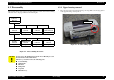
3. Disconnect the cable from the connector (CN2) on the main board using tweezers,
etc.
4. Take out the 2 screws.
Figure 4-10. Removing the PS unit
5. Pull the PS unit out while lifting up on it.
C.B.P 3×8
C.B.S 3×6
PS unit
CN2
When installing the PS unit, make sure the claws are attached to
the hooks on the lower housing.
Figure 4-11. Reassembling the PS unit
Do not insert the pin of the PS cable to the leftmost side of the
connector because the 1st pint of its cable is cut.
Figure 4-12. Connecting the PS cable(CN2)
Tightening Torque for screw
- C.B.S 3x6 : 6+/-1 kgf.cm
- C.B.P 3x8 : 6+/-1 kgf.cm
2
22
2
5
Blue line
marking
3 4