SERVICE MANUAL Color Inkjet Printer Stylus C40UX/C40SX/C20UX/C20SX ® SEIJ01002
Notice All rights reserved. No part of this manual may be reproduced, stored in a retrieval system, or transmitted in any form or by any means electronic, mechanical, photocopying, or otherwise, without the prior written permission of SEIKO EPSON CORPORATION. All effort have been made to ensure the accuracy of the contents of this manual. However, should any errors be detected, SEIKO EPSON would greatly appreciate being informed of them.
PRECAUTIONS Precautionary notations throughout the text are categorized relative to 1)Personal injury and 2) damage to equipment. DANGER Signals a precaution which, if ignored, could result in serious or fatal personal injury. Great caution should be exercised in performing procedures preceded by DANGER Headings. WARNING Signals a precaution which, if ignored, could result in damage to equipment.
About This Manual This manual describes basic functions, theory of electrical and mechanical operations, maintenance and repair procedures of the printer. The instructions and procedures included herein are intended for the experienced repair technicians, and attention should be given to the precautions on the preceding page. Manual Configuration This manual consists of six chapters and Appendix. CHAPTER 1. PRODUCT DESCRIPTIONS Provides a general overview and specifications of the product. CHAPTER 2.
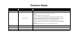
Revision Status Revision Issued Date A May 31. 2001 First Release July 10. 2001 Chapter 2 • Page 38 : Ink consumption of Initial charge was revised. Chapter 4 • Page 58 : Warning message was deleted. • Page 61 : Caution message regarding disassembly and assembly was added. • Page 63 : Adjustment Requested message for Top Margin adjustment was added. • Page 65 : Reassembly message for inserting PS cable was revised. • Page 68~70 : Disassembly procedure for Paper Guide Upper/Left was added.
CONTENTS Chapter 1 PRODUCT DESCRIPTION 1.1 FEATURES ......................................................................................................... 9 1.7 INK CARTRIDGE ........................................................................................... 23 1.7.1 Black Ink Cartridge ................................................................................... 23 1.7.2 Color Ink Cartridge .................................................................................... 23 1.
4.1.2 Tools .......................................................................................................... 59 4.1.3 Screws ........................................................................................................ 59 4.1.4 Work Completion Check ........................................................................... 60 4.2 Disassembly ....................................................................................................... 4.2.1 Upper housing removal ..............
CHAPTER 1 PRODUCT DESCRIPTION
Stylus C40UX/C40SX/C20UX/C20SX 1.1 FEATURES High color print quality - 1440 (H) x 720 (V) dpi printing - 4 color printing (YMCK) Revision B 1.2 Differences between the Stylus C20 and the Stylus C40 The Stylus C20 and Stylus C40 are mechanically the same, but the throughput of the Stylus C40 is slightly higher than that of the Stylus C20. (Refer to Table 1-1.) Table 1-1.
Stylus C40UX/C40SX/C20UX/C20SX 1.3 SECIFICATIONS This section covers specifications of the printer. 1.3.1 Physical Specification Weight : 2.48kg (without the ink cartridges) Dimension : 424 mm(W) x 227 mm (D) x 168 mm (H) (Printing) Revision B 1.3.
Stylus C40UX/C40SX/C20UX/C20SX Revision B 1.3.3 Paper Feeding 1.3.5 Electrical specification Feeding method : Friction feed with ASF 120 V version Paper path : Cut-sheet ASF (Top entry) Rated voltage : AC 120 V Feed speed : Input voltage range : AC 99 - 132 V Rated frequency range : 50 - 60 Hz Feed condition Time Speed 10.16mm(0.4 inch) feed 110msec 92.36mm (3.64inch)/sec Input frequency range : 49.5 - 60.5 Hz Continuous feed 140msec 139.7mm (5.
Stylus C40UX/C40SX/C20UX/C20SX Revision B 1.3.6 Envirormental Condition 1.3.8 Safety Approvals Temperature 120 V version : : 10 to 35 ºC (operating *3 ) : -20 to 60 ºC(non-operating, *1) 1 month at 40 ºC 120 hours at 60 ºC Humidity : 20 to 80% RH (operating, *2,*3) : 5 to 85% RH (non-operating, *1, *2) Resistance to shock : 1 G, within 1 ms (operating) : 2 G, within 2 ms (non-operating, *1) Resistance to vibration : 0.15G (operating) : 0.
Stylus C40UX/C40SX/C20UX/C20SX Revision B 1.4 INTERFACE 1.4.2 Parallel Interface (Forward Channel) Interface specification for each model are as the following. Parallel Interface :EPSON Stylus C40SX .EPSON Stylus C20SX USB Interface :EPSON Stylus C40UX .EPSON Stylus C20UX *This printer interface as standard. 1.4.
Stylus C40UX/C40SX/C20UX/C20SX Revision B Connector pin assignment and signals : Parameter Minimum Maximum Parameter Minimum Maximum Pin No.
Stylus C40UX/C40SX/C20UX/C20SX Revision B Pin No. Signal Name Return GND pin In/Out 17 Chassis GND - - Chassis GND. 16, 33 19-30 GND - - Signal GND. 15, 34 NC - - Not connected. Functional description * In/Out refers to the direction of signal flow from the printer's point of view. 1.4.
Stylus C40UX/C40SX/C20UX/C20SX Revision B Extensibility Request : The printer responds affirmatively when the extensibility request values are 00H or 04H, that mean, 00H : Request Nibble Mode Reverse Channel Transfer. 04H : Request Device ID; Return Data Using Nibble Mode Rev Channel Transfer. busy state. This slowdown is started when the rest of the input buffer becomes several hundreds of bytes. Finally, the printer is in the busy state continuously when the input buffer is full.
Stylus C40UX/C40SX/C20UX/C20SX Revision B 1.4.5 IEEE1284.4 Protocol The packet protocol described by IEEE1284.4 standard allows a device to carry on multiple exchanges or conversations which contain data and/or control information with another device at the same time across a single point-to-point link. The protocol is not, however, a device control language. It does provide basic transport-level flow control and multiplexing services.
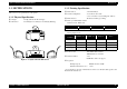
Stylus C40UX/C40SX/C20UX/C20SX Revision B 1.5 OPERATOR CONTROLS 1.5.4 Printer Condition and Panel Status Indicators 1.5.1 Operate Switch Printer status Operate switch is located on the control panel. Power ON condition Powe Error Priority On - 10 1.5.2 Control Panel Ink sequence Blink - 6 Switches Ink Cartridge change mode Blink - 5 Data processing Blink - 9 Paper Out *1 - On 4 (1) Power (green) Lights when the operate switch is "ON", and AC power is supplied.
Stylus C40UX/C40SX/C20UX/C20SX Revision B 1.5.5 Printer Initialization 1.5.6 Errors There are three kinds of initialization method. Ink out (1) Power-on initialization This printer is initialized when turning the printer power on, or printer recognized the cold-reset command (remote RS command). When printer is initialized, following action is performed. (a) Initializes printer mechanism. (b) Clears input data buffer. (c) Clears print buffer. (d) Sets default values.
Stylus C40UX/C40SX/C20UX/C20SX Revision B 1.6 PAPER Quality 1.6.1 Paper Handling : #10,DL,C6 Bond paper, Plain paper, Air mail : CHOUKEI4,3 Kraft, new Kent paper : YOUKEI1,2,3,4 Kraft, new Kent paper * Envelope printing is only available at normal temperature. * Keep the longer side of the envelope horizontally at setting. Do not perform reverse feed more than 0 mm(0”). Exclusive paper 1.6.
Stylus C40UX/C40SX/C20UX/C20SX < Photo Quality Glossy Film > Size : A4 (210mm x 297mm) Revision B 1.6.3 Printing Area Cut Sheet : A6 (105mm x 148mm) : Letter (216mm x 279mm) Thickness : 0.13 mm(0.005") Weight : N/A Size : A4 (210mm x 297mm) : Letter (216mm x 279mm) Thickness : 0.23 mm(0.009") Weight : 167 g/m 2 (44 lb.143Kg) < Iron-on Cool Peel Transfer Paper > Size Thickness Weight : A4 (210mm x 297mm) : Letter (216mm x 279mm) : 0.18 mm(0.
Stylus C40UX/C40SX/C20UX/C20SX Revision B Envelope Raster Graphics mode PW (Paper width) (typ.) PL (Paper length) (typ.) A4 210mm (8.3”) 297mm (11.7”) 3mm 3mm 3mm 14mm (0.54”) (0.12”) (0.12”) (0.12”) /3mm (0.12”) 21mm (0.83”) /3mm (0.12”) Letter 216mm (8.5”) 279mm (11.0”) 3mm 3mm 3mm 14mm (0.54”) (0.12”) (0.12”) (0.12”) /3mm (0.12”) 21mm (0.83”) /3mm (0.12”) B5 182mm (7.2”) 257mm (10.1”) 3mm 3mm 3mm 14mm (0.54”) (0.12”) (0.12”) (0.12”) /3mm (0.12”) 21mm (0.83”) /3mm (0.
Stylus C40UX/C40SX/C20UX/C20SX Revision B 1.7 INK CARTRIDGE 1.7.1 Black Ink Cartridge Type : Exclusive cartridge Color : Black Print capacity : 270 pages / A4 (ISO/IEC10561 Letter Pattern at 360 dpi) Ink life : 2 years from production date Storage temperature : -20°C - 40°C (Storage, within a month at 40°C) : -30°C - 40°C (Packing storage, within a month at 40°C) : -30°C - 60°C (Transit, within 120 hours at 60°C and within a month at 40) Dimension : 19.8 mm(W) x 52.7 mm(D) x 38.5 mm(H) 1.7.
CHAPTER 2 OPERATING PRINCIPLES
Stylus C40UX/C40SX/C20UX/C20SX Revision B 2.1 Overview Paper Eject Roller This section describes the operating principles of the printer mechanism and electrical circuit boards. The Stylus C40UX/C40SX/C20UX/C20SX has only the following two circuit boards: Main board: C413 MAIN/MAIN-B Power supply board: C417 PSB/PSE PF Motor PF Roller Star Wheel Roller 2.1.1 Printer Mechanism CR Timing belt CR unit The printer mechanism for Stylus C40UX/C40SX/C20UX/C20SX is designed newly.
Stylus C40UX/C40SX/C20UX/C20SX Revision B 2.1.2 Printhead Head Driver Board The printhead uses a new developed U-CHIPS head and Stylus C40UX/C40SX/ C20UX/C20SX can perform multiple shot printing and variable printing. Printhead nozzle configuration is as follows.
Stylus C40UX/C40SX/C20UX/C20SX Revision B 2.1.2.1 Printing Process 2.1.2.2 Printing Method This section explains the process in which the printheads of On-Demand inkjet printers eject ink from each nozzle. For print dot system, Stylus C40UX/C40SX/C20UX/C20SX has the following two kinds of printing modes. 1. Normal State: When no printing signal is sent from PC, or no PZT drive voltage is applied, PZT does not change shape, therefore PZT does not squeeze the cavity.
Stylus C40UX/C40SX/C20UX/C20SX Revision B 2.1.3 Carriage Mechanism The carriage mechanism consists of Carriage motor (CR motor), Carriage unit (including printhead), CR timing belt, CR guide shaft, CR guide frame, CR home & I/C detector (HP/PE/IC sensor) etc. The carriage mechanism moves the carriage back and forth according to the drive from the carriage motor. The following stepping motor is mounted to drive CR mechanism. (See the table below.
Stylus C40UX/C40SX/C20UX/C20SX Revision B Also, when replacing ink use this lever to confirm whether the cover cartridge is open or closed. There are separate replacement positions for replacing the Black and Color ink cartridges. If the cover cartridge is open, the I/C detection plate makes contact with the HP/IC detection lever, causing the HP/IC sensor to detect a high signal.
Stylus C40UX/C40SX/C20UX/C20SX Revision B 2.1.4 Paper Feeding Mechanism Table 2-2. PF Motor Specifications The paper feeding mechanism consists of Paper feed motor (PF motor), PF roller, Paper eject roller, Star wheel roller, and so on. The paper feeding mechanism feeds paper loaded from ASF using the PF roller and Paper Eject Roller & Star wheel roller. For this mechanism, the PF motor mentioned in the right Table 2-2 is used on this product.
Stylus C40UX/C40SX/C20UX/C20SX Revision B Additionally, the top & end of the paper is detected with the HP/PE/IC sensor. In case the PE sensor dose not detect the paper in the paper loading sequence, the printer detects the “Paper out error”. If the paper is detected after complete the paper eject sequence, the printer detects the “Paper jam error”. Drive sent from the PF motor is always transmitted to the ASF unit side.
Stylus C40UX/C40SX/C20UX/C20SX Revision B Transfer the PF motor drive to LD roller PF Motor Pinion Gear (CW) → Spur Gear 60 (PF Roller) (CCW) → Spur Gear 10.8 (CCW) → Combination Gear 18, 28 (CW) → Spur Gear 27.2 (CCW) → Spur Gear 25.6 (CW) → Change Laver rotates (CW) → Combination Gear 16, 32 (CCW) → Spur Gear 35.2 (CW) (include the clutch mechanism) → LD Roller (CW) Following Figure 2-9 shows the PF motor drive transmission path to the LD roller unit built in the ASF unit.
Stylus C40UX/C40SX/C20UX/C20SX NOTE: Revision B Step1 Spur gear 35.2 Step2 Clutch gear Change Lever Step3 Tension spring 0.143 LD roller shaft The Clutch gear is molded on the back side of the Spur gear 35.2 such as Combination gear. Clutch Clutch lever Clutch lock tooth Figure 2-11. Disengage & Clutch mechanism The Clutch mechanism transmits the PF motor drive to the LD roller shaft only when the Clutch gear rotates CW direction after the Change lever releases the Clutch lever.
Stylus C40UX/C40SX/C20UX/C20SX Revision B Step 1 Step 2 Hopper LD roller LD roller shaft When the paper is advanced with the PF roller, Change lever push down the Clutch lever as right figure and the Clutch lock tooth is disengaged from the Clutch gear. As the result, the drive from the PF motor is interrupted and the LD roller dose not rotate. This position is the ASF home position. The Paper return plate is set to avoid that the paper is slipped down from the paper set position.
Stylus C40UX/C40SX/C20UX/C20SX Revision B 2.1.6 Ink System Mechanism Table 2-4. PF motor rotational direction & Ink System Mechanism Directions Ink system mechanism consists of pump unit (include the CR lock lever) and capping mechanism. Ink system mechanism drives the pump unit that presses cap to the printhead and ejects ink from ink cartridge, head cavity and cap to the waste ink pad. Functions Counterclockwise (*1) • Absorbs ink by the pump unit • Set the CR lock lever 2.1.6.
Stylus C40UX/C40SX/C20UX/C20SX Revision B 2.1.6.2 Capping Mechanism The capping mechanism covers the printheads with the cap holder to prevent the nozzle from increasing viscosity when the printer is in stand-by mode or when the printer is off. This product has valveless cap system. Air valve function used for the previous models pumps and ejects ink only inside the cap by absorbing ink with the valve open.
Stylus C40UX/C40SX/C20UX/C20SX Revision B 2.1.6.2.2 Non porous pad in cap Due to this, the cap is newly designed as follows. Stylus COLOR 480 Stylus C40/C20 seal rubber porous pad ink eject hole Figure 2-18. non porous pad in cap (Stylus C40/C20) The cap unit used for the previous models has the porous pad to keep the moisture in the cap and prevent that the air bubble occurs in CL sequence. To get the same effects on new cap unit without the porous pad.
Stylus C40UX/C40SX/C20UX/C20SX Revision B CL2 2.1.7 Ink Sequence Initial ink charge After the product is purchased and the printer is turned on for the first time, the printer must be performed the initial ink charge and charges ink inside the head cavity. When the initial ink charge is completed properly, the printer releases the flag inside the EEPROM and no initial ink charge will be performed next time the power is turned on.
Stylus C40UX/C40SX/C20UX/C20SX Revision B Flashing This printer performs the following two kinds of the Flashing for the following purpose. Periodical Flashing This is due to avoid the increment of both ink’s viscosity in the printhead nozzle during the continuous printing and the specific small amount of the ink is ejected in the cap based on the periodical flashing timer.
Stylus C40UX/C40SX/C20UX/C20SX Revision B 2.1.8 Printing mode Table 2-6. Printing mode for Black mode The print resolution and printing method are determined automatically by setting the media type and print quality (It is able to set by slider bar) in the printer driver as following table. Following table show you the detail setting in the “Auto” mode.
Stylus C40UX/C40SX/C20UX/C20SX Revision B 2.2 Electrical Circuit Operating Principles The electric circuit of the Stylus C40UX/C40SX/C20UX/C20SX consists of the following boards. Main board: C413 MAIN (USB) C413 MAIN-B (Parallel) Power supply board: C417 PSB/PSE Board 2.2.1 C417 PSB/PSE board The power supply boards of Stylus C40UX/C40SX/C20UX/C20SX use a RCC (Ringing Chalk Converter) circuit, which generates +36VDC for drive line and +5VDC for logic line to drive the printer.
Stylus C40UX/C40SX/C20UX/C20SX +36VDC Revision B The C417 PSB/PSE board has the various control circuits to stop voltage output if a malfunction occurs on the power supply board or the main board while the printer mechanism is on duty. Following explains each control and protection circuit. +5VDC ZD53 +36V line constant voltage control circuit: +5VDC line over voltage limitation +36VDC over current protection The output level of +36V line is monitored by a R92, R93,Q91,ZD51.
Stylus C40UX/C40SX/C20UX/C20SX Revision B 2.2.2 C413 MAIN/B Board 2.2.2.1 Main elements The printer mechanism is controlled by C413MAIN. On this MAIN board, 3.3V regulator IC is not mounted and all IC is driven with 5.0 V. See Figure for the C413 MAIN/B board block diagram. Table 2-8 shows the function of the each main elements on C413MAIN. PROM 4M (IC6) Address Data D-RAM 1M (IC5) Reset IC (IC2) Table 2-8.
CHAPTER 3 TROUBLESHOOTING
Stylus C40UX/C40SX/C20UX/C20SX Revision B 3.1 Overview Table 3-1. Motor, Coil Resistance This chapter describes how to identify troubles in two levels: unit level repair and component level repair. Refer to the flowchart in this chapter to identify the defective unit and perform component level repair if necessary. This chapter also explains motor coil resistance, sensor specification and error indication. Motor Location Check Point Resistance CR Motor CN12 Pin 1 and 3 Pin 2 and 4 9.
Stylus C40UX/C40SX/C20UX/C20SX Revision B 3.2 Troubleshooting with LED Error Indications This section describes how to troubleshoot the problem when the printer indicates an error at power on and can not print. The Stylus C40UX/C40SX/C20UX/C20SX can detect the following six errors and seven status, and indicates them with the LEDs, as shows below. See the following tables which show the error conditions and corresponding possible causes: Table 3-4.
Stylus C40UX/C40SX/C20UX/C20SX Revision B Table 3-4. Error Condition and possible cause (continued) Symptom Possible Cause Check table Any error indication is not displayed. But, the paper is not ejected completely. Paper jam dose not occur. • Paper eject roller gear is disengaged from the pump’s gears. • The Paper eject frame is not assembled in the Paper eject frame. Dot missing occur and it is not recovered with CL • Pump unit dose not absorb the ink from the printhead.
Stylus C40UX/C40SX/C20UX/C20SX Revision B Table 3-6. Paper out error indication Step No. Detail phenomenon ASF LD roller dose not attempt to load the paper. But, the PF motor and the Spur gear 35.2 is rotating. Check point • Check if the clutch tooth is broken. Table 3-7. Paper out error indication Remedy Step No. • Replace the LD unit with new one. Clutch tooth 3 4 If it is no problem, proceed the next step. 1. Set the tension spring 0.143 in the clutch mechanism.
Stylus C40UX/C40SX/C20UX/C20SX Revision B Table 3-8. Paper jam error indication Step No. Detail phenomenon Check point Table 3-9. Paper jam error indication Remedy Step No. Detail phenomenon • Check if the star wheel • Replace the Paper eject assembly is assembled frame with new one. in the Paper eject frame. 1 Paper is not ejected completely and jammed around the Paper eject frame. 3 Star wheel assy Paper is loaded correctly from ASF.
Stylus C40UX/C40SX/C20UX/C20SX Revision B Table 3-11. Paper Jam Error indication Table 3-10. Paper jam error indication Step No. Detail phenomenon The PF roller continues to turn when the printer’s power is turned on. Check point Remedy 1. If the Torsion spring 0.22 is not set on the correct position, set it correctly. If any paper dust is placed around the PE sensor Tension Spring 0.22 lever, remove it. 2. If the Torsion spring 0.22 is not set on the correct position, set it correctly.
Stylus C40UX/C40SX/C20UX/C20SX Revision B Table 3-13. Multiple papers are always loaded Step No. 1 Detail phenomenon Any error indication is not displayed on the monitor. But, multiple papers are always loaded from ASF. Check point Check if the Paper return plate is operating correctly in the ASF when the paper is loaded. Remedy Table 3-15. Fatal Error indication Step No. Detail phenomenon Check point 1. Check if the compression spring 1.47 is installed securely on the change lever.
Stylus C40UX/C40SX/C20UX/C20SX Revision B Table 3-16. Paper is not ejected completely without any error indication Step No. 1 Detail phenomenon Printing is normal. But, the paper is not ejected completely and the bottom area stay around the Paper eject frame. Check point Remedy 1. Check if the Paper eject roller rotate when the paper is ejected. 1. Assemble the Spur gear 60 to the PF motor pinion. Table 3-17. Dot missing occur and it is not recovered with CL Step No.
Stylus C40UX/C40SX/C20UX/C20SX Revision B Table 3-18. Dot missing occur and it is not recovered with CL Step No. Detail phenomenon Check point 5. Check if the Pump tube is connected to the bottom of the Cap assembly correctly 1 In the CL sequence, the pump unit seems work correctly. But, any ink is not ejected to waste ink pad. Moreover, any ink is not absorbed from the head to the cap. Pump tube connection point 6.
Stylus C40UX/C40SX/C20UX/C20SX Revision B . Table 3-20. Print quality is not good Step No. Detail phenomenon Vertical banding is appeared against the CR movement direction. And it looks like uneven printing. Check point Remedy 1. Check if each segment is printed correctly in the nozzle check pattern. 2. Check if the CR rail 1. Perform the CL and check the nozzle check pattern. on the main frame is not extremely dirty, etc. 3.
Stylus C40UX/C40SX/C20UX/C20SX Revision B Table 3-22. Print quality is not good Step No. 3 4 Detail phenomenon Check point Remedy 1. Use the suitable paper according to the driver setting. Printing is blurred 1. Check if the suitable paper is used according to the printer driver setting. 2. Check if the correct head ID is stored in the EEPROM by using the Adjustment program. 1. Clean the ink stained parts with soft cloth. Ink stains the paper 1. Check if the following parts are stained with ink.
CHAPTER 4 DISASSEMBLY AND ASSEMBLY
Stylus C40UX/C40SX/C20UX/C20SX Revision B 4.1 Overview 4.1.1 Precautions This section describes procedures for disassembling the main components of the Stylus C40UX/C40SX/C20UX/C20SX. Unless otherwise specified, disassembly units or components can be reassembled by reversing the disassembly procedure. Things, if not strictly observed, that could result in injury or loss of life are described under the heading “Warning”.
Stylus C40UX/C40SX/C20UX/C20SX W A R N IN G Revision B Avant de commencer, assurez vous que l’imprimante soit eteinte et que le cordon d’alimentation soit debranche. Lorsque vous changez la pile au lithium, assurez vous que la nouvelle respecte bien les caracteristiques requises. Lorque que vous installez la pile au lithium, faites attention a l’inserer dans le bon sens en respectant la polarite. Veillez a jeter les piles usagees selon le reglement local. Ne rechargez pas les piles au lithium.
Stylus C40UX/C40SX/C20UX/C20SX Revision B 4.1.2 Tools 4.1.3 Screws Use only specified tools to avoid damaging the printer. Table 4-2. No. Table 4-1. Name Supplier Outward Form Parts No. Phillips Screw Driver (No.1) EPSON B743800100 Phillips Screw Driver (No.2) EPSON B743800200 Nipper EPSON B740500100 Tweezers EPSON B741000100 Disassembly and Assembly Name and Specification Overview 1 CBS 3x6 2 CBP 3x8 3 CBS (P2) 3x6 4 CBS 3x8 5 C.P.F.
Stylus C40UX/C40SX/C20UX/C20SX Revision B 4.1.4 Work Completion Check Table 4-3. Work Completion Check (continued) Classification If any service is made to the printer, use the checklist shown below to confirm all works are completed properly and the printer is ready to be returned to the user. Table 4-3.
Stylus C40UX/C40SX/C20UX/C20SX Revision B 4.2 Disassembly 4.2.1 Upper housing removal The flowchart below shows step-by-step disassembly procedures. When disassembling each unit, refer to the page number shown in the figure. 1. Upper housing removal Page 61 ASF unit removal Page 63 PS unit removal Page 65 Move the edge guide to the right until it stops moving. Make sure the edge guide is in the upper housing’s notch position.
Stylus C40UX/C40SX/C20UX/C20SX 2. Revision B Remove the 2 hooks at the front using a precision screwdriver (-). C A U T IO N 3. Remove the 2 hooks on the sides by pushing the tops of the hooks up. The printer should not turn when the front 2 hooks are removed. Upper housing Figure 4-4. Removing the side hook 4. Remove the 3 hooks at the back using a (-) screwdriver or similar tool. Figure 4-3. Removing the front hook Figure 4-5.
Stylus C40UX/C40SX/C20UX/C20SX Revision B 4.2.2 ASF unit removal 1. Remove the upper housing. (Refer to Section 4.2.1) 2. Take out the three screws. A D J U S T M E N T R E Q U IR E D The Top Margin adjustment is required when the ASF unit is replaced. CBP 3×8 CBS (P2) 3×6 3 1 CBP 3×6 2 Figure 4-6. Removing the ASF unit 3. Pull the ASF unit toward the rear and remove it. When installing the ASF unit, install the spring in the guide, then install it while supporting it by hand. Figure 4-7.
Stylus C40UX/C40SX/C20UX/C20SX Revision B 4.2.3 Waste ink pad removal 1. Remove the upper housing. (Refer to Section 4.2.1) 2. Remove the ASF unit. (Refer to Section 4.2.2) 3. Remove the Waste ink pad. A D J U S T M E N T R E Q U IR E D When the Waste ink pad is replaced with a new one, following service item is required. Waste ink counter reset operation. (Refer to Section 5.1.12) Waste ink pad tube stopper Figure 4-8.
Stylus C40UX/C40SX/C20UX/C20SX Revision B 4.2.4 PS unit removal When installing the PS unit, make sure the claws are attached to the hooks on the lower housing. 1. Remove the upper housing. (Refer to Section 4.2.1) 2. Remove the ASF unit. (Refer to Section 4.2.2) 3. Disconnect the cable from the connector (CN2) on the main board using tweezers, etc. 4. Take out the 2 screws. CN2 PS unit Figure 4-11. Reassembling the PS unit C.B.
Stylus C40UX/C40SX/C20UX/C20SX Revision B 4. 4.2.5 Paper eject roller removal 1. Remove the upper housing. (Refer to Section 4.2.1) 2. Grip the dowel pin of the PE roller’s gear, turn it clockwise and release the carriage lock. Protrusion Take out the two screws. CBS 3×6 Figure 4-14. Take out the screw 5. Return the carriage to the home position, then remove the Front Frame. Figure 4-13. Releasing the carriage lock 3. Move the carriage to the center. Front Frame Figure 4-15.
Stylus C40UX/C40SX/C20UX/C20SX 6. Revision B Slide the PE roller to the left side, then remove the claw extending from the lower housing. C A U T IO N Paper Eject roller If the Paper eject roller gear and Paper eject roller shaft are removed or , make sure that neither of the Paper eject roller shaft hooks is damaged. If either of the hooks is damaged, it should be replaced with a new one. hook Figure 4-16. Releasing the claw extending 7.
Stylus C40UX/C40SX/C20UX/C20SX 4.2.6 Paper Guide Upper/Left removal C A U T IO N Revision B 3. Press the dowel of the paper guide unit with tweezers, etc., then pull it forward and remove it. Perform this operation by the following procedures so that the coating material of the PF roller does not damage. 1. Remove the upper housing. (Refer to Section 4.2.1) 2.
Stylus C40UX/C40SX/C20UX/C20SX Revision B 1. Insert the tip of the spring to the Paper Guide. 3. Assemble the Paper Guide Upper/Left to the Main Frame. Figure 4-21. Setting the spring to the Paper Guide Figure 4-23. Assembling the Paper Guide 1 2. Place the OHP sheet on the PF roller. 4. Fix the dowel of the Paper Guide Upper/Left to the hole of the Main Frame by sliding the Paper Guide Upper/Left to the right side. And, release the spring from the hook of the Paper Guide Upper/Left.
Stylus C40UX/C40SX/C20UX/C20SX Revision B 5. Eject the OHP sheet from the printer by rotating the protrusion of the Paper Eject roller gear in CW direction. Protrusion Figure 4-25.
Stylus C40UX/C40SX/C20UX/C20SX Revision B 5. 4.2.7 MAIN board removal 1. Remove the upper housing. (Refer to Section 4.2.1) 2. Remove the ASF unit. (Refer to Section 4.2.2) 3. Remove the PS unit. (Refer to Section 4.2.4) 4. Remove the two hooks, then remove the Switch cover. Remove the three screws, then remove the shield cover. USB Type CBS 3×6 Switch cover Parallel Type Hooks C.P.F.S-Tight 3×12 Figure 4-26. Removing the Switch cover CBS 3×6 Figure 4-27.
Stylus C40UX/C40SX/C20UX/C20SX 6. Disconnect the four connectors (CN9, CN4, CN7, CN12). Revision B 8. Lift the MAIN board up and remove it. Tightening Torque for screw USB Type - C.B.S 3x6 screw - C.B.S 3x8 screw Parallel Type - C.B.S 3x6 screw - C.P.F.S-Tight 3x12 screw - C.B.S 3x8 screw CN9 CN4 : 9+/-1 kgf.cm : 9+/-1 kgf.cm : 9+/-1 kgf.cm : 9+/-1 kgf.cm : 9+/-1 kgf.cm CN7 CN12 A D J U S T M E N T R E Q U IR E D Figure 4-28. Disconnecting the connectors 7. Take out the 1 screw.
Stylus C40UX/C40SX/C20UX/C20SX Revision B 5. 4.2.8 CR motor removal 1. Remove the upper housing. (Refer to Section 4.2.1) 2. Move the carriage to the center. 3. Press on the driven pulley and loosen the timing belt, then remove the timing belt from the CR pinion gear. Disconnect connector CN7 from the MAIN board then disconnect the cable. When reassembling the CR motor, it contact the lib of Main frame after turning clockwise. Timing belt lib Driven pulley CR pinion gear Figure 4-30.
Stylus C40UX/C40SX/C20UX/C20SX Revision B 6. 4.2.9 Printhead unit removal 1. Remove the upper housing. (Refer to Section 4.2.1) 2. Remove the ink cartridges. 3. Move the carriage to the center. 4. Press on the driven pulley and loosen the timing belt, then remove the timing belt from the CR pinion gear. Press on the left and right inside of the carriage unit, then pull the unit forward and remove the cover. Carriage cover Timing belt Driven pulley CR pinion gear Figure 4-33.
Stylus C40UX/C40SX/C20UX/C20SX 8. Revision B Disconnect the FFC from the connector. A D J U S T M E N T R E Q U IR E D FFC When the Printhead is replaced with a new one, following adjustments must be performed in the order below: Refer to Table 5-1 1. Initial ink charge 2. Head ID input 3. Bi-D adjustment When the Printhead is removed and reinstalled, only the following adjustment is required. Refer to Table 5-1 1. Head cleaning 2. Bi-D adjustment Figure 4-37.
Stylus C40UX/C40SX/C20UX/C20SX Revision B 4.2.10 LD unit removal When reassembling the LD unit, make sure that seven hooks are 1. Remove the upper housing. (Refer to Section 4.2.1) 2. Remove the ASF unit. (Refer to Section 4.2.2) 3. Disconnect the cables which are connected to the LD unit. 4. Disconnect connector CN4 form the MAIN board. set to the Main frame. LD unit Figure 4-40. Setting seven hooks Cables A D J U S T M E N T R E Q U IR E D Figure 4-38. Disconnecting the Cables 5.
Stylus C40UX/C40SX/C20UX/C20SX Revision B 4.2.11 Printer mechanism removal 1. Remove the upper housing. (Refer to Section 4.2.1) 2. Remove the ASF unit. (Refer to Section 4.2.2) 3. Remove the PS unit. (Refer to Section 4.2.4) 4. Remove the Printhead unit. (Refer to Section 4.2.9) 5. Remove the Paper eject roller. (Refer to Section 4.2.5) A D J U S T M E N T R E Q U IR E D When the Printer mechanism with a new one, following adjustments must be performed in the order below: Refer to Table 5-1 1.
CHAPTER 5 ADJUSTMENT
Stylus C40UX/C40SX/C20UX/C20SX Revision B 5.1 Overview This section describes the procedure for adjustments required when the printer is disassembled and assembled for repair or service. 5.1.1 Required Adjustment Table 5-1 lists all the necessary adjustments for this printer. If any service listed in this table is carried out, all adjustments corresponding to that service item should be performed to ensure proper operation of the printer. Table 5-1.
Stylus C40UX/C40SX/C20UX/C20SX Revision B 2. 5.1.2 Adjustment Program Initial Setting menu Select the Interface port number which you connect the printer to your PC. You have to input the following four items before entering the adjustment main menu. Model name (Stylus C40UX/40SX/20UX/20SX) For the Stylus C40UX, select Model name “Stylus C40UX.” Interface setting (LPT1, LPT2, LPT3, EPUSB1, EPUSB2, EPUSB3) 1. When you run this program, the following menu appears.
Stylus C40UX/C40SX/C20UX/C20SX Revision B The user interface of the main menu on this program is shown below. 5.1.3 Adjustment Program feature The adjustment program enables you to set various values correctly to prevent malfunction and fluctuation of printing quality and printing function caused by difference in components and assembly when the printer components are replaced during repair. Basic adjustment items by using this program are shown as fellows.
Stylus C40UX/C40SX/C20UX/C20SX Revision B Get status This function is used to get the printer status and following figure is displayed on the screen by clicking the “Get status” button. This function can get the printer status even if the printer is error condition except the main logic circuit failure, and control the printer by using the D4 mode functions. C A U T IO N This program dose not display the “Paper out” error status in the Bi-d adjustment even if the paper is out in the ASF.
Stylus C40UX/C40SX/C20UX/C20SX Revision B 5.1.4 EEPROM initial setting 5.1.5 Head ID This function is used when replacing the MAIN board. This adjustment function is required when any of the following parts is replaced. Using this function enables writing of the initial setting values to the new MAIN board’s EEPROM. 1. Choose the “EEPROM initial setting” in the Adjustment menu.
Stylus C40UX/C40SX/C20UX/C20SX 4. Choose the “Check present data” and click the OK button. Following Check present data menu is displayed. Click the OK button, then readout data is displayed. Revision B 5. Figure 5-8. Read out the Head ID from the EEPROM Adjustment Choose the “Change data” item in the Head ID input menu and click the OK button. Following Head ID input menu is displayed. Input a 6-digit code of the Head Voltage ID in the following menu. Figure 5-9. Entering the 6-digits Head ID 6.
Stylus C40UX/C40SX/C20UX/C20SX Revision B 5.1.6 Bi-D You perform this adjustment to correct differences in printing positions, which is caused by incorrect of printing timing in right and left directions during the Bidirectional printing. Therefore, you are required to perform this adjustment after performing the following operations. Replacing the Print mechanism Replacing the main board Replacing the CR motor Figure 5-11. Bi-d adjustment pattern Replacing the Printhead 1.
Stylus C40UX/C40SX/C20UX/C20SX 5. Revision B By choosing the misaligned dot size, following input menu for the adjustment value is displayed. Check the printed pattern again and Input the suitable value in the following menu and click the “OK” button. The input value is written in the specific address of the EEPROM. 5.1.7 USB ID When you replace the main board with a new one, you have to input the USB ID newly into the specific address of the EEPROM.
Stylus C40UX/C40SX/C20UX/C20SX Revision B 2. C A U T IO N 1. In case the USB ID is not input in the adjustment program after the main board is replaced to new one, the USB ID may not possibly unique one. In this case, the USB ID conflicts another peripheral USB ID in the USB port driver and the another USB peripheral may not possibly be used with the USB. Choose the “Input USB ID” and click “OK” button in the “USB ID check/Input” menu. Following menu is displayed.
Stylus C40UX/C40SX/C20UX/C20SX Revision B 2. 5.1.8 Top margin Choose the “Print the Top margin” in the “Top margin adjustment” and click the “OK” button. This function can be used to change the top margin value. You are required to perform this adjustment after performing the following operations. Removing or replacing the ASF unit. Removing or replacing the LD unit. Replacing the Printer mechanism Replacing the main board 1. Choose the “Top margin” in the Adjustment menu. Figure 5-17.
Stylus C40UX/C40SX/C20UX/C20SX 5. Revision B The selected value is stored in EEPROM after you select the adjustment value and click 5.1.9 Head cleaning This printhead cleaning is CL1’ and about 1/8 of the brand-new black I/C and 1/17 of the brand-new color I/C are consumed. Before use this function, check the remaining ink amount of the both I/C by using the “Get status” function. 1. Choose the “Head cleaning” in the Maintenance menu. Figure 5-18. Top margin adjustment input menu 6.
Stylus C40UX/C40SX/C20UX/C20SX Revision B 5.1.10 Initial ink charge 5.1.11 Refurbishment for DOA After you replaced any of the following units, perform initial ink charge and return the printer after making sure that ink is ejected correctly from the printhead. If you clean the cavity of the printhead and cap assembly, this function will be useful.
Stylus C40UX/C40SX/C20UX/C20SX 2. Set the dummy cartridge in the printer using the ink replacement function. 3. Select “Yes” under “Item,” then click the “OK” button. The “Refurbishment for DOA” function is then executed.
Stylus C40UX/C40SX/C20UX/C20SX Revision B 2. 5.1.12 Protection counter check The program allows you to check or clear the current protection counter value (waste ink amount counter). After read the Caution description on the above menu, click the “OK” button in the menu. The present counter value is displayed on the bottom column as following figure. Check the present counter value 1. Choose the “Check the present counter values” in the “Maintenance” menu and click the “OK” button. Figure 5-23.
Stylus C40UX/C40SX/C20UX/C20SX Revision B Clear the present counter value 1. Choose the “Clear the present counter values” in the “Maintenance” menu and click the “OK” button. C A U T IO N Be sure to replace the installed waste ink pad with a new one after or before you clear the current protection counter value. C H E C K P O IN T The initial value of the Protection counter is differ by destination as bellow: ESP : 0 Excepting ESP: 2940 Figure 5-24. Choose the Clear the present counter value 2.
Stylus C40UX/C40SX/C20UX/C20SX Revision B 5.1.13 EEPRON check You can check the EEPROM data or can write the specific data into the specific address of the EEPROM directly even if the printer is error condition. (In case one of the main logic circuit such as CPU, I/F receiver IC, RAM, EEPROM is broken, this function is not available) Select the “EEPROM check” function in the Maintenance menu. The main menu of this function is as following figure. The following two functions are built in this program.
Stylus C40UX/C40SX/C20UX/C20SX Revision B 5.1.14 EEPROM back up data This function is used when replacing the MAIN board. Using this function, the data on the currently used MAIN board are backed up, then the backed up data can be written to the EEPROM on the new MAIN board after replacement. Figure 5-30. Replace the defective main board with new one C H E C K P O IN T 1. This function may fail. If it fails, replace the MAIN board with a new one, then carry out the specified adjustments in order. 3.
Stylus C40UX/C40SX/C20UX/C20SX Revision B 5.1.15 A4 pattern will print We recommend to use this function to check the repaired product quality in your final stage of your repair. The following 6 items are printed on the check pattern. C H E C K P O IN T The check point for the first black and each color solid pattern (beta pattern 360 x 360dpi normal dot) in the A4 Check pattern is as follows. -Any white line is not observed. -Uneven banding is not observed extremely.
Stylus C40UX/C40SX/C20UX/C20SX Revision B Figure 5-32.
CHAPTER 6 MAINTENANCE
Stylus C40UX/C40SX/C20UX/C20SX Revision B 6.1 Overview This section provides information to maintain the printer in its optimum condition. 6.1.1 Cleaning This printer has no mechanical components which require regular cleaning except the printhead. Therefore, when returning the printer to the user, check the following parts and perform appropriate cleaning if stain is noticeable.
Stylus C40UX/C40SX/C20UX/C20SX Revision B 6.1.2 Service Maintenance 6.1.3 Lubrication If print irregularity (missing dot, white line, etc.) has occurred or the printer indicates “Maintenance Error”, take the following actions to clear the error. The characteristics of the grease have great affects on the mechanical function and durability, especially does the characteristics about temperature environment.
Stylus C40UX/C40SX/C20UX/C20SX Revision B Table 6-2. Lubrication Type/Point No. Lubrication Type/Point Remarks 1 • Specified area on the Main frame. Refer to Figure 6-1, "Lubrication point 1". • G-58 • 100mg x 4 points • Use a brush to apply it. • After lubrication, move the CR unit left or right and smooth out the grease on the Front frame. 2 • Specified area on the Front frame.
Stylus C40UX/C40SX/C20UX/C20SX Revision B G-58 200mm Figure 6-2. Lubrication point 2 G-46 Figure 6-3.
CHAPTER19 7 APPENDIX
Stylus C40UX/C40SX/C20UX/C20SX Revision B 7.1 Connector Summary Table 7-1. Connector Summary for C413MAIN/B Connector Function Table to refer to 7.1.1 Major Component Unit CN9 For connection with the Print Head Table 7-5 The Major component units of this printer are as follows.
Stylus C40UX/C40SX/C20UX/C20SX Revision B Table 7-5.
Stylus C40UX/C40SX/C20UX/C20SX Revision B 7.2 EEPROM Address Map Table 7-7. EEPROM Address Map Address Explanation Setting QPIT setting Factory setting 00H 00H 00H 00H 00H 00H 00H 00H 00H 00H 04H 04H*a 00H (*1)*e 00H (*1)*e 00H 00H 00H 00H 00H 00H 0FH 00H 00H 10H | 13H 00H | 00H 00H | 00H 00H | 00H 00H | 00H Table 7-7.
Stylus C40UX/C40SX/C20UX/C20SX Revision B Table 7-7.
Stylus C40UX/C40SX/C20UX/C20SX Address Explanation Revision B Setting Factory setting Address Explanation 00H (*1) 47H Head Actuator Rank ID for IwB 48H Setting QPIT setting Factory setting +30<=n<=+70 00H (*1) Head Actuator Rank ID for IwC +30<=n<=+70 00H (*1) 49H Head Actuator Rank ID for IwM +30<=n<=+70 00H (*1) 35H Bi-D Adjustment 3 (for Variable shot) 36H Reserved 00H 00H 37H Reserved 00H 00H 38H Reserved 00H 00H 39H 1stDot Position Adjustment 00H (*1) 4AH
Stylus C40UX/C40SX/C20UX/C20SX Revision B Customer name *a : D4mode setting (EEPROM 09H) USB Bit5 Bit4 Bit3 Bit2 Bit1 Bit0 Customer name 0 0 0 0 Bit3 Bit2 D4mode 0 0 0 0 Auto 0 0 0 0 0 1 Acer 0 1 On 0 0 0 0 1 0 Apple 1 0 Off 0 0 0 0 1 1 Compaq 0 0 0 1 0 0 Dell 0 0 0 1 0 1 eMachines 0 0 0 1 1 0 Fujitsu 0 0 0 1 1 1 Hewlett-Packard 0 0 1 0 0 0 IBM 0 0 1 0 0 1 Gateway 0 0 1 0 1 0 NEC 0 0 1 0 1 1 Panasonic Pa
Stylus C40UX/C40SX/C20UX/C20SX Revision B 7.3 Component Layout Figure 7-2. C413MAIN component layout Figure 7-3.
Stylus C40UX/C40SX/C20UX/C20SX Revision B Figure 7-5. C417PSE component layout Figure 7-4.
Stylus C40UX/C40SX/C20UX/C20SX Revision B 7.4 Parts List Table 7-8. parts list Table 7-8. parts list Ref No. Description 601 "POROUS PAD,TUBE,STOPPER" Ref No. Description 602 "SHIELD PLATE,M/B" 100 "HOUSING,UPPER,USB" 603 "C.B.P-TITE SCREW,3X8,F/ZN" 101 "COVER,PRINTER,USB" 604 C.B.S. SCREW(B300204211) 102 PAPER SUPPORT 700 EDGE GUIDE 103 STACKER 701 HOPPER 104 LOGO PLATE 10X40;C 702 "PAD,HOPPER" 105 "BUTTON,SW" 703 "COMPRESSION SPRING,2.50" 200 "BOARD ASSY.
Stylus C40UX/C40SX/C20UX/C20SX Revision B 7.5 Exploded Diagram Following pages shows exploded diagram. 104 105 100 102 101 103 Figure 7-6.
Stylus C40UX/C40SX/C20UX/C20SX Revision B for 220V for 120V 300 except ETT 200 400 forEURO,EAI(220V),ASIA(220V), EAL,RUSSIA Figure 7-7.
Stylus C40UX/C40SX/C20UX/C20SX Revision B 508 503 B 507 D 506 505 504 C 501 A 513 X 2 502 513 509 F 511 513 512 500 510 511 511 511 SOFigure S 7-8.
Stylus C40UX/C40SX/C20UX/C20SX Revision B 604 604 604 604 604 602 603 600 601 Figure 7-9.
Stylus C40UX/C40SX/C20UX/C20SX Revision B 604 605 605 604 604 602 603 600 601 Figure 7-10.
Stylus C40UX/C40SX/C20UX/C20SX Revision B 700 701 704 702 710 703 705 706 708 707 709 Figure 7-11.
Stylus C40UX/C40SX/C20UX/C20SX Revision B 7.