EPSON RC+ 7.0 Option AOI (Add-On Instructions) Rev.
EPSON RC+ 7.0 Option AOI (Add-On Instructions) Rev.
EPSON RC+ 7.0 Option AOI (Add-On Instructions) Rev.1 Copyright 2020 SEIKO EPSON CORPORATION. All rights reserved. EPSON RC+ 7.0 Option AOI (Add-On Instructions) Rev.
FOREWORD Thank you for purchasing our robot products. This manual contains the information necessary for the correct use of the Manipulator. Please carefully read this manual and other related manuals before installing the robot system. Keep this manual handy for easy access at all times. WARRANTY The robot and its optional parts are shipped to our customers only after being subjected to the strictest quality controls, tests, and inspections to certify its compliance with our high performance standards.
TRADEMARKS Microsoft, Windows, and Windows logo are either registered trademarks or trademarks of Microsoft Corporation in the United States and/or other countries. Allen-Bradley and Studio 5000 are registered trademarks of Rockwell Automation, Inc.. Other brand and product names are trademarks or registered trademarks of the respective holders.
iv EPSON RC+ 7.0 Option AOI (Add-On Instructions) Rev.
Table of Contents 1. Introduction 1 2. Operation 1 2.1 Requirements ...........................................................................................1 2.2 Robot Controller Preparation ...................................................................1 2.3 PLC Project Preparation ..........................................................................1 2.4 SPEL AOI Common Inputs and Outputs..................................................1 2.5 SPEL AOI General Operation ...................
Table of Contents SPEL_Jump3CP ........................................................................................... 40 SPEL_Lefty ................................................................................................... 41 SPEL_LimZ ................................................................................................... 42 SPEL_LocalGet ............................................................................................ 43 SPEL_LocalSet ...................................
1. Introduction 1. Introduction This manual contains instructions on how to use EPSON RC+ 7.0 SPEL AOI (Add-OnInstructions). AOI allows Allen-Bradley® PLC users to execute commands in EPSON robot controllers from a PLC ladder logic program. EPSON AOI uses extended remote I/O to communicate with the controller via EtherNet/IP. 2. Operation 2.1 Requirements To use SPEL Add-On-Instructions, the following are required: - An EPSON robot controller with an EtherNet/IP Fieldbus slave board installed.
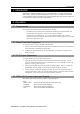
3. Configuring the Robot Controller Outputs: InCycle Done Error ErrCode1 and ErrCode2 BOOL output bit that indicates the status of execution of the AOI. If this is high, then the AOI is executing. BOOL output bit that indicates the status of completion of the AOI. If this is high, then the AOI execution is complete. BOOL output bit that indicates if an error occurred during execution. INT error codes from the robot controller.
3. Configuring the Robot Controller 5. Expand [Fieldbus Slave] in the tree and select [Ethernet/IP]. Set the IP address, mask, and gateway that will be used for communication from the A1 EtherNet module in the PLC. 6. Select [Remote Control]-[PLC] and select Allen-Bradley® as the PLC Vendor. 7. Click “Close” on the [System Configuration] dialog. The controller will restart. EPSON RC+ 7.0 Option AOI (Add-On Instructions) Rev.
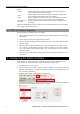
4. Creating a PLC Project using SPEL AOIs 4. Creating a PLC Project using SPEL AOIs EPSON RC+ 7.0 users are provided with Allen-Bradley® Logix Designer files which are installed on the user PC by the EPSON RC+ v7.5.0 or greater installer. The files are located in \EpsonRC70\Fieldbus\EtherNetIP\AOI on the user PC. In this chapter, we will show how to create a simple example project to turn robot motors on and off using SPEL AOIs.
4. Creating a PLC Project using SPEL AOIs 3. The dialog shown below will be displayed. Leave all choices as default, then click . 4. You have just created a new empty PLC project 5. Now you need to add and configure the Ethernet module for communications with the robot controller. There are two methods: Import the file EpsonEtherNetIP.L5X, or perform manual configuration. EPSON RC+ 7.0 Option AOI (Add-On Instructions) Rev.
4. Creating a PLC Project using SPEL AOIs Importing the Ethernet configuration 1. Right click on [A1, Ethernet], then click [Import Module]. 2. Navigate to \EpsonRC70\Fieldbus\EtherNetIP\AOI and select the file EpsonEtherNetIP.L5X. 3. After import, right-click on the module and select Properties. Change the default IP address to be the address of the robot controller's EtherNetIP slave board. Manual Ethernet configuration 1. Right click on [A1, Ethernet], then click [New Module]. 6 EPSON RC+ 7.
4. Creating a PLC Project using SPEL AOIs 2. Type in “generic” in the search field. Click “ETHERNET MODULE” under catalog number, then click . 3. Enter the values as shown, and use the IP address of the robot controller EtherNet/IP slave, then click . 4. Click on the next window. Saving your project at this stage is a good idea. When creating a new Ethernet module, please note that connection parameter values should match your robot controller values. EPSON RC+ 7.
4. Creating a PLC Project using SPEL AOIs Import SPEL AOIs in to the new project 1. Now you need to import AOIs in the new project. For this example, you will import all SPEL AOIs. You can also import individual AOIs. To do this, right click on [Add-On Instructions] folder from [Controller Organizer], click [Import Add-On Instruction]. 2. 8 Navigate to \EpsonRC70\Fieldbus\EtherNetIP\AOI, then select “SPEL_All.L5X” file and click . EPSON RC+ 7.0 Option AOI (Add-On Instructions) Rev.
4. Creating a PLC Project using SPEL AOIs 3. The dialog below is displayed. Check to make sure that there are no errors, then click . 4. Now you should see the list of all SPEL AOIs in the project. EPSON RC+ 7.0 Option AOI (Add-On Instructions) Rev.
4. Creating a PLC Project using SPEL AOIs 5. 10 Now you can create a program. 5-1. Expand [MainProgram], then double click on [MainRoutine]. 5-2. Click [Favorites] tab, add 5 extra rungs. Then drag “Examine On” and “Output Energize” to rung 0, 2 and 4. 5-3. Click [Add-On] tab, drag “SPEL_Init” to rung 1, “SPEL_MotorOn” to rung 3, and “SPEL_MotorOff” to rung 5, like shown below. EPSON RC+ 7.0 Option AOI (Add-On Instructions) Rev.
4. Creating a PLC Project using SPEL AOIs 6. In rung 0, double click at [?] of “Examine On”, type in the name of the variable. In this case we will use “InitSwitch”. 7. Do the same step as above, in rung 0, double click on [?] of the “Output Energize”, and type “InitCoil”. Right click on [InitSwitch], click on [New “InitSwitch”], then click , as shown below. 8. 9. Create new variable “InitCoil” same method used in “InitSwitch”. 10.
4. Creating a PLC Project using SPEL AOIs 11-4. Click [?] next to [ExtInputs], type “Ep”, it will auto populate, press . 11-5. Do same step to [ExtOutputs]. “SPEL_Init” is now configured and the rung lines should change from red to blue. 11-6. Do the same steps as in 11-1 to 11-2 for rung 3 and 5. Choose “MotorOn” for rung 3, “MotorOff” for rung 5. 11-7. Do the same steps as in 11-3 for rung 3 and 5. Use “MotorOnCoil” for rung 3, “MotorOffCoil” for rung 5. 12. The program in now complete.
4. Creating a PLC Project using SPEL AOIs 16. PLC now in run mode and program is ready to be executed. EPSON RC+ 7.0 Option AOI (Add-On Instructions) Rev.
5. SPEL AOI Reference 5. SPEL AOI Reference In this chapter each SPEL AOI is described. For AOI operation in general, refer to section 2.5, SPEL AOI General Operation. For each AOI in the Operation section, there is also a referal to the corresponding SPEL+ command in the SPEL+ Language Reference manual which has more details about the command. Each AOI has a simple example. SPEL_Above Description Sets the elbow orientation of the specified point to Above. Common inputs and Outputs Refer to section 2.
5. SPEL AOI Reference SPEL_Accel Description Sets the point to point acceleration and deceleration. Specifies the ratio (%) of the maximum acceleration/deceleration using an integer equals to or greater than 1. Common inputs and Outputs Refer to section 2.4 SPEL AOI Common Inputs and Outputs. Inputs Accel Decel INT value of acceleration as percentage. INT value of deceleration as percentage. Operation Refer to section 2.5 SPEL AOI General Operation.
5. SPEL AOI Reference SPEL_AccelS Description Sets acceleration and deceleration. Specifies the value which is the actual acceleration/deceleration in linear or CP motion (Unit: mm/sec2). Common Inputs and Outputs Refer to section 2.4 SPEL AOI Common Inputs and Outputs. Inputs Accel Decel REAL value of acceleration. REAL value of deceleration. Operation Refer to section 2.5 SPEL AOI General Operation. Refer to AccelS Statement in the SPEL+ Language Reference manual. Example To set acceleration to 100.
5. SPEL AOI Reference SPEL_Arc Description Moves the arm from the current position to the specified position in circular interpolation motion on XY plane face. Common Inputs and Outputs Refer to section 2.4 SPEL AOI Common Inputs and Outputs. Inputs midPoint endPoint INT middle point in Arc command. INT end point in Arc command. Operation Refer to section 2.5 SPEL AOI General Operation. Refer to Arc Statement in the SPEL+ Language Reference manual.
5. SPEL AOI Reference SPEL_Arc3 Description Moves the arm from the current position to the specified position in circular interpolation in 3 dimensions. Common Inputs and Outputs Refer to section 2.4 SPEL AOI Common Inputs and Outputs. Inputs midPoint endPoint INT middle point in Arc3 command. INT end point in Arc3 command. Operation Refer to section 2.5 SPEL AOI General Operation. Refer to Arc3 Statement in the SPEL+ Language Reference manual.
5. SPEL AOI Reference SPEL_ArchGet Description Gets the Arch parameter. Common Inputs and Outputs Refer to section 2.4 SPEL AOI Common Inputs and Outputs. Inputs ArchNum INT desired Arch number. Outputs DepartDist ApproachDist INT departing distance of the given Arch number. INT approaching distance of the given Arch number. Operation Refer to section 2.5 SPEL AOI General Operation. Refer to Arch Function in the SPEL+ Language Reference manual.
5. SPEL AOI Reference SPEL_ArchSet Description Sets the Arch parameter. Common Inputs and Outputs Refer to section 2.4 SPEL AOI Common Inputs and Outputs. Inputs ArchNum DepartDist ApproachDist INT desired Arch number. REAL departing distance of the given Arch number. REAL approaching distance of the given Arch number. Operation Refer to section 2.5 SPEL AOI General Operation. Refer to Arch Statement in the SPEL+ Language Reference manual. Example To set 60.0, 60.
5. SPEL AOI Reference SPEL_BaseGet Description Gets the base coordinate system. Common Inputs and Outputs Refer to section 2.4 SPEL AOI Common Inputs and Outputs. Inputs NumAxes INT number of robot axes. For a SCARA robot, use 4. For a 6-axis robot, use 6. Outputs BaseX BaseY BaseZ BaseU BaseV BaseW REAL base value of coordinate X. REAL base value of coordinate Y. REAL base value of coordinate Z. REAL base value of coordinate U. REAL base value of coordinate V. REAL base value of coordinate W.
5. SPEL AOI Reference SPEL_BaseSet Description Sets the base coordinate system. Common Inputs and Outputs Refer to section 2.4 SPEL AOI Common Inputs and Outputs. Inputs NumAxes BaseX BaseY BaseZ BaseU BaseV BaseW INT number of robot axes. For a SCARA robot, use 4. For a 6-axis robot, use 6. REAL base value of coordinate X. REAL base value of coordinate Y. REAL base value of coordinate Z. REAL base value of coordinate U. REAL base value of coordinate V. REAL base value of coordinate W.
5. SPEL AOI Reference SPEL_Below Description Sets the elbow orientation of the specified point to Below. Common Inputs and Outputs Refer to section 2.4 SPEL AOI Common Inputs and Outputs. Inputs Point INT desired point number. Operation Refer to section 2.5 SPEL AOI General Operation. Refer to Elbow Statement in the SPEL+ Language Reference manual. Example To set orientation of P2 to below, enter 2 as point. As shown below. EPSON RC+ 7.0 Option AOI (Add-On Instructions) Rev.
5. SPEL AOI Reference SPEL_CPOff Description Turns off Continuous Path parameter. Common Inputs and Outputs Refer to section 2.4 SPEL AOI Common Inputs and Outputs. Operation Refer to section 2.5 SPEL AOI General Operation. Refer to CP Statement in the SPEL+ Language Reference manual. Example To set CP to off, run the AOI like as shown below. 24 EPSON RC+ 7.0 Option AOI (Add-On Instructions) Rev.
5. SPEL AOI Reference SPEL_CPOn Description Turns on Continuous Path parameter. Common Inputs and Outputs Refer to section 2.4 SPEL AOI Common Inputs and Outputs. Operation Refer to section 2.5 SPEL AOI General Operation. Refer to CP Statement in the SPEL+ Language Reference manual. Example To set CP to On, run the AOI as shown below. EPSON RC+ 7.0 Option AOI (Add-On Instructions) Rev.
5. SPEL AOI Reference SPEL_ExecCmd Description The SPEL_ExecCmd AOI is used by other AOIs to execute a command in the robot controller. 26 EPSON RC+ 7.0 Option AOI (Add-On Instructions) Rev.
5. SPEL AOI Reference SPEL_FineGet Description Gets the setting of positioning end judgement range for all joints. Outputs Axis INT position accuracy for each joint in encoder pulses. Operation Refer to section 2.5 SPEL AOI General Operation. Refer to Fine Function in the SPEL+ Language Reference manual. Example To get the position accuracy for the robot, run the AOI as shown below. EPSON RC+ 7.0 Option AOI (Add-On Instructions) Rev.
5. SPEL AOI Reference SPEL_FineSet Description Sets the positioning end judgement range for all joints. Common Inputs and Outputs Refer to section 2.4 SPEL AOI Common Inputs and Outputs. Inputs Axis1..Axis6 INT position accuracy for each joint in encoder pulses. Operation Refer to section 2.5 SPEL AOI General Operation. Refer to Fine Statement in the SPEL+ Language Reference manual. Example To set the position accuracy for the robot, enter the Axis values and run the AOI as shown below. 28 EPSON RC+ 7.
5. SPEL AOI Reference SPEL_Flip Description Sets the wrist orientation of the specified point to Flip. Common Inputs and Outputs Refer to section 2.4 SPEL AOI Common Inputs and Outputs. Inputs Point INT desired point number. Operation Refer to section 2.5 SPEL AOI General Operation. Refer to Wrist Statement in the SPEL+ Language Reference manual. Example To set orientation of robot point P2 to flip, enter 2 as the point number and run the AOI as shown below. EPSON RC+ 7.
5. SPEL AOI Reference SPEL_Go Description Moves from the current position to the specified position in PTP motion. Common Inputs and Outputs Refer to section 2.4 SPEL AOI Common Inputs and Outputs. Inputs Point INT desired point number. Operation Refer to section 2.5 SPEL AOI General Operation. Refer to Go Statement in the SPEL+ Language Reference manual. Example To move the robot to point 0 using PTP motion, enter “0” as the point and run the AOI, as shown below. 30 EPSON RC+ 7.
5. SPEL AOI Reference SPEL_In Description Reads a byte of input. Common Inputs and Outputs Refer to section 2.4 SPEL AOI Common Inputs and Outputs. Inputs PortNum INT desired input byte port number. Outputs Value INT value of the desired input port. Operation Refer to section 2.5 SPEL AOI General Operation. Refer to In Function in the SPEL+ Language Reference manual. Example To read input port number 66, set [PortNum] to “66”. EPSON RC+ 7.0 Option AOI (Add-On Instructions) Rev.
5. SPEL AOI Reference SPEL_InertiaGet Description Gets the load inertia. Common Inputs and Outputs Refer to section 2.4 SPEL AOI Common Inputs and Outputs. Outputs Inertia Eccentricity REAL acquired Inertia. REAL acquired Eccentricity. Operation Refer to section 2.5 SPEL AOI General Operation. Refer to Inertial Function in the SPEL+ Language Reference manual. Example To read load Inertia and Eccentricity, run the AOI, as shown below. 32 EPSON RC+ 7.0 Option AOI (Add-On Instructions) Rev.
5. SPEL AOI Reference SPEL_InertiaSet Description Sets the load inertia. Common Inputs and Outputs Refer to section 2.4 SPEL AOI Common Inputs and Outputs. Inputs Inertia Eccentricity REAL desired Inertia. REAL desired Eccentricity. Operation Refer to section 2.5 SPEL AOI General Operation. Refer to Inertia Statement in the SPEL+ Language Reference manual. Example To set load Inertia and Eccentricity to 0.01, 0.01 respectively, enter the values and run the AOI. EPSON RC+ 7.
5. SPEL AOI Reference SPEL_Init Description Initializes the PLC program for SPEL AOI execution. It is required to execute SPEL_Init before executing any other AOIs. Note: If the controller has a system error, then it must be reset before SPEL_Init and other SPEL AOIs can execute successfully. Common Inputs and Outputs Refer to section 2.4 SPEL AOI Common Inputs and Outputs. Operation Refer to section 2.5 SPEL AOI General Operation. Example As shown below, toggle [Init Switch] to high to start the AOI.
5. SPEL AOI Reference EPSON RC+ 7.0 Option AOI (Add-On Instructions) Rev.
5. SPEL AOI Reference SPEL_InW Description Returns the status if an input word. Common Inputs and Outputs Refer to section 2.4 SPEL AOI Common Inputs and Outputs. Inputs PortNum INT desired port number. Operation Refer to section 2.5 SPEL AOI General Operation. Refer to InW Function in the SPEL+ Language Reference manual. Example To read content of port number 33, enter the value and run the AOI. 36 EPSON RC+ 7.0 Option AOI (Add-On Instructions) Rev.
5. SPEL AOI Reference SPEL_Jog Description Jogs the robot. Common Inputs and Outputs Refer to section 2.4 SPEL AOI Common Inputs and Outputs. Inputs JogMode Axis Distance INT desired mode. 0=World, 1=Joint. INT desired axis. REAL value: World: X,Y,Z in mm. U,V,W in deg. Joint: J1-J6 in deg. Operation Refer to section 2.5 SPEL AOI General Operation. Example To move robot in -Y direction for 40mm, enter values and run the AOI as shown below. EPSON RC+ 7.0 Option AOI (Add-On Instructions) Rev.
5. SPEL AOI Reference SPEL_Jump Description Moves the arm using gate motion for a SCARA robot. Common Inputs and Outputs Refer to section 2.4 SPEL AOI Common Inputs and Outputs. Inputs Point INT desired point. Operation Refer to section 2.5 SPEL AOI General Operation. Refer to Jump Statement in the SPEL+ Language Reference manual. Example To move the robot to point P2 using gate trajectory, enter the value for Point and run the AOI as shown below. 38 EPSON RC+ 7.0 Option AOI (Add-On Instructions) Rev.
5. SPEL AOI Reference SPEL_Jump3 Description Moves the arm with 3D gate motion for a 6-axis robot. This is a combination of two CP motion and one PTP motion. Common Inputs and Outputs Refer to section 2.4 SPEL AOI Common Inputs and Outputs. Inputs DepartPoint INT desired depart point. ApproPoint INT desired approach point. DestPoint INT desired destination point. Operation Refer to section 2.5 SPEL AOI General Operation. Refer to Jump3CP Statement in the SPEL+ Language Reference manual.
5. SPEL AOI Reference SPEL_Jump3CP Description Moves the arm with 3D gate motion for a 6-axis robot. This is a combination of three CP motions. Common Inputs and Outputs Refer to section 2.4 SPEL AOI Common Inputs and Outputs. Inputs DepartPoint INT desired depart point. ApproPoint INT desired approach point. DestPoint INT desired destination point. Operation Refer to section 2.5 SPEL AOI General Operation. Refer to Jump3CP Statement in the SPEL+ Language Reference manual.
5. SPEL AOI Reference SPEL_Lefty Description Sets the hand orientation of the specified point to Lefty. Common Inputs and Outputs Refer to section 2.4 SPEL AOI Common Inputs and Outputs. Inputs Point INT desired point number. Operation Refer to section 2.5 SPEL AOI General Operation. Refer to Hand Statement in the SPEL+ Language Reference manual. Example To change P2’s hand orientation to Lefty, enter values and run the AOI as shown below. EPSON RC+ 7.0 Option AOI (Add-On Instructions) Rev.
5. SPEL AOI Reference SPEL_LimZ Description Sets the initial Joint #3 height (Z coordinate value) in Jump command. Common Inputs and Outputs Refer to section 2.4 SPEL AOI Common Inputs and Outputs. Inputs Height REAL desired Z limit in mm. Operation Refer to section 2.5 SPEL AOI General Operation. Refer to LimZ Statement in the SPEL+ Language Reference manual. Example To set LimZ value of 10mm, enter values and run the AOI as shown below. 42 EPSON RC+ 7.0 Option AOI (Add-On Instructions) Rev.
5. SPEL AOI Reference SPEL_LocalGet Description Gets data for a given local coordinate system. Common Inputs and Outputs Refer to section 2.4 SPEL AOI Common Inputs and Outputs. Inputs NumAxes LocalNum INT number of axes in the robot. For SCARA, use 4, for Articulate robot, use 6. INT desired local number you want to get. Outputs LocalX LocalY LocalZ LocalU LocalV LocalW REAL the coordinate value of that axis. REAL the coordinate value of that axis. REAL the coordinate value of that axis.
5. SPEL AOI Reference SPEL_LocalSet Description Sets the local coordinate number. Common Inputs and Outputs Refer to section 2.4 SPEL AOI Common Inputs and Outputs. Inputs NumAxes LocalNum LocalX LocalY LocalZ LocalU LocalV LocalW INT number of axes in the robot. For SCARA, use 4, for Articulate robot, use 6. INT desired local number you want to get. REAL the desired coordinate value of X axis. REAL the desired coordinate value of Y axis. REAL the desired coordinate value of Z axis.
5. SPEL AOI Reference SPEL_MemIn Description Reads a byte of memory IO. Common Inputs and Outputs Refer to section 2.4 SPEL AOI Common Inputs and Outputs. Inputs PortNum INT port number to be read. Port number refers to byte number. Outputs Value INT value of the port. Operation Refer to section 2.5 SPEL AOI General Operation. Refer to MemIn Function in the SPEL+ Language Reference manual. Example To read port number 0 of memory I/O, run the AOI as shown below. EPSON RC+ 7.
5. SPEL AOI Reference SPEL_MemInW Description Reads a word of memory IO. Common Inputs and Outputs Refer to section 2.4 SPEL AOI Common Inputs and Outputs. Inputs PortNum INT port number to be read. Outputs Value INT value of the port. Operation Refer to section 2.5 SPEL AOI General Operation. Refer to MemInW Function in the SPEL+ Language Reference manual. Example To read port number 0 as word, run the AOI as shown below. 46 EPSON RC+ 7.0 Option AOI (Add-On Instructions) Rev.
5. SPEL AOI Reference SPEL_MemOff Description Turns a memory IO bit off. Common Inputs and Outputs Refer to section 2.4 SPEL AOI Common Inputs and Outputs. Inputs Bit INT bit number to be turned off. Operation Refer to section 2.5 SPEL AOI General Operation. Refer to MemOff Statement in the SPEL+ Language Reference manual. Example To turn off memory bit number 3, run the AOI as shown below. EPSON RC+ 7.0 Option AOI (Add-On Instructions) Rev.
5. SPEL AOI Reference SPEL_MemOn Description Turns a memory IO bit on. Common Inputs and Outputs Refer to section 2.4 SPEL AOI Common Inputs and Outputs. Inputs Bit INT bit number to be turned on. Operation Refer to section 2.5 SPEL AOI General Operation. Refer to MemOn Statement in the SPEL+ Language Reference manual. Example To turn on memory bit number 3, run the AOI as shown below. 48 EPSON RC+ 7.0 Option AOI (Add-On Instructions) Rev.
5. SPEL AOI Reference SPEL_MemOut Description Sets a byte of memory IO. Common Inputs and Outputs Refer to section 2.4 SPEL AOI Common Inputs and Outputs. Inputs PortNum OutData INT desired output port number. INT value of the data to be sent to output port. Operation Refer to section 2.5 SPEL AOI General Operation. Refer to MemOut Statement in the SPEL+ Language Reference manual. Example To send 99 to port number 4, run the AOI as shown below. EPSON RC+ 7.0 Option AOI (Add-On Instructions) Rev.
5. SPEL AOI Reference SPEL_MemOutW Description Sets a word of memory IO. Common Inputs and Outputs Refer to section 2.4 SPEL AOI Common Inputs and Outputs. Inputs PortNum OutData INT desired output port number. INT value of the data need to be sent to output port. Operation Refer to section 2.5 SPEL AOI General Operation. Refer to MemOutW Statement in the SPEL+ Language Reference manual. Example To send 99 to port number 15, run the AOI as shown below. 50 EPSON RC+ 7.
5. SPEL AOI Reference SPEL_MemSw Description Reads a single bit of memory IO. Common Inputs and Outputs Refer to section 2.4 SPEL AOI Common Inputs and Outputs. Inputs Bit INT desired memory bit number. Operation Refer to section 2.5 SPEL AOI General Operation. Refer to MemSw Function in the SPEL+ Language Reference manual. Example To read memory bit number 5, run the AOI as shown below. EPSON RC+ 7.0 Option AOI (Add-On Instructions) Rev.
5. SPEL AOI Reference SPEL_MotorOff Description Turns robot motors off. Common Inputs and Outputs Refer to section 2.4 SPEL AOI Common Inputs and Outputs. Operation Refer to section 2.5 SPEL AOI General Operation. Refer to Motor Statement in the SPEL+ Language Reference manual. Example To turn off motors, run the AOI as shown below. 52 EPSON RC+ 7.0 Option AOI (Add-On Instructions) Rev.
5. SPEL AOI Reference SPEL_MotorOn Description Turns robot motors on. Common Inputs and Outputs Refer to section 2.4 SPEL AOI Common Inputs and Outputs. Operation Refer to section 2.5 SPEL AOI General Operation. Refer to Motor Statement in the SPEL+ Language Reference manual. Example To turn on motors, run the AOI as shown below. EPSON RC+ 7.0 Option AOI (Add-On Instructions) Rev.
5. SPEL AOI Reference SPEL_Move Description Moves the arm from the current position to the specified position in a linear interpolation motion. Common Inputs and Outputs Refer to section 2.4 SPEL AOI Common Inputs and Outputs. Inputs Point INT desired point number. Operation Refer to section 2.5 SPEL AOI General Operation. Refer to Move Statement in the SPEL+ Language Reference manual. Example To move the end effector to point P1, run the AOI as shown below. 54 EPSON RC+ 7.
5. SPEL AOI Reference SPEL_NoFlip Description Sets the wrist orientation of the specified point to NOFLIP. Common Inputs and Outputs Refer to section 2.4 SPEL AOI Common Inputs and Outputs. Inputs Point INT desired point number. Operation Refer to section 2.5 SPEL AOI General Operation. Refer to Wrist Statement in the SPEL+ Language Reference manual Example To set point P2 orientation to NoFlip, run the AOI as shown below. EPSON RC+ 7.0 Option AOI (Add-On Instructions) Rev.
5. SPEL AOI Reference SPEL_Off Description Turns an output bit off. Common Inputs and Outputs Refer to section 2.4 SPEL AOI Common Inputs and Outputs. Inputs Bit INT desired output bit number. Operation Refer to section 2.5 SPEL AOI General Operation. Refer to Off Statement in the SPEL+ Language Reference manual. Example To turn off bit number 4, run the AOI as shown below. 56 EPSON RC+ 7.0 Option AOI (Add-On Instructions) Rev.
5. SPEL AOI Reference SPEL_On Description Turns an output bit on. Common Inputs and Outputs Refer to section 2.4 SPEL AOI Common Inputs and Outputs. Inputs Bit INT desired output bit number. Operation Refer to section 2.5 SPEL AOI General Operation. Refer to On Statement in the SPEL+ Language Reference manual. Example To turn on bit number 4, run the AOI as shown below. EPSON RC+ 7.0 Option AOI (Add-On Instructions) Rev.
5. SPEL AOI Reference SPEL_Out Description Sets an output byte to a given value. Common Inputs and Outputs Refer to section 2.4 SPEL AOI Common Inputs and Outputs. Inputs PortNum outData INT desired output port number. INT desired output port value. Operation Refer to section 2.5 SPEL AOI General Operation. Refer to Out Statement in the SPEL+ Language Reference manual. Example To set port number 1 with value of 99, run the AOI as shown below. 58 EPSON RC+ 7.0 Option AOI (Add-On Instructions) Rev.
5. SPEL AOI Reference SPEL_OutW Description Sets an output word to a given value. Common Inputs and Outputs Refer to section 2.4 SPEL AOI Common Inputs and Outputs. Inputs PortNum outData INT desired output port number. INT desired output port value. Operation Refer to section 2.5 SPEL AOI General Operation. Refer to OutWStatement in the SPEL+ Language Reference manual. Example To set port number 0 with value of 99, run the AOI as shown below. EPSON RC+ 7.0 Option AOI (Add-On Instructions) Rev.
5. SPEL AOI Reference SPEL_PowerHigh Description Sets the power level of robot to high. Common Inputs and Outputs Refer to section 2.4 SPEL AOI Common Inputs and Outputs. Operation Refer to section 2.5 SPEL AOI General Operation. Refer to Power Statement in the SPEL+ Language Reference manual. Example To set power high to the robot, run the AOI as shown below. 60 EPSON RC+ 7.0 Option AOI (Add-On Instructions) Rev.
5. SPEL AOI Reference SPEL_PowerLow Description Sets the power level of robot to low. Common Inputs and Outputs Refer to section 2.4 SPEL AOI Common Inputs and Outputs. Operation Refer to section 2.5 SPEL AOI General Operation. Refer to Power Statement in the SPEL+ Language Reference manual. Example To set power low to the robot, run the AOI as shown below.. EPSON RC+ 7.0 Option AOI (Add-On Instructions) Rev.
5. SPEL AOI Reference SPEL_ResetError Description Reset the robot controller AOI error state. After an error has occurred while executing a SPEL AOI, you must execute SPEL_ResetError successfully before you can execute another AOI. Note: If the controller has a system error, then it must be reset before SPEL_Init and other SPEL AOIs can execute successfully. Common Inputs and Outputs Refer to section 2.4 SPEL AOI Common Inputs and Outputs. 62 EPSON RC+ 7.0 Option AOI (Add-On Instructions) Rev.
5. SPEL AOI Reference SPEL_Righty Description Sets the hand orientation of the specified point to Righty. Common Inputs and Outputs Refer to section 2.4 SPEL AOI Common Inputs and Outputs. Inputs Point INT desired point. Operation Refer to section 2.5 SPEL AOI General Operation. Refer to Hand Statement in the SPEL+ Language Reference manual Example To set orientation of P2 to Righty, run the AOI as shown below. EPSON RC+ 7.0 Option AOI (Add-On Instructions) Rev.
5. SPEL AOI Reference SPEL_SavePoints Description Saves the current point data in robot controller memory to the default point file for robot 1 (robot1.pts) in the robot controller. To use this command, a valid RC+ project must exist in the controller. Typically, SavePoints is used to save points taught using the SPEL_Teach AOI. When the controller starts up, it loads the project and the default point file, so the saved points are in memory. Common Inputs and Outputs Refer to section 2.
5. SPEL AOI Reference SPEL_Speed Description Sets the arm speed setting for PTP motion. Common Inputs and Outputs Refer to section 2.4 SPEL AOI Common Inputs and Outputs. Inputs Speed ApproSpeed DepartSpeed INT desired speed. INT desired approach speed, units are %. INT desired depart speed, units are %. Operation Refer to section 2.5 SPEL AOI General Operation. Refer to Speed Statement in the SPEL+ Language Reference manual.
5. SPEL AOI Reference SPEL_SpeedS Description Sets the arm speed setting of CP motion. This will set the depart, and approach speed as well. Common Inputs and Outputs Refer to section 2.4 SPEL AOI Common Inputs and Outputs. Inputs Speed ApproSpeed DepartSpeed INT desired speed. INT desired approach speed. INT desired depart speed. Operation Refer to section 2.5 SPEL AOI General Operation. Refer to SpeedS Statement in the SPEL+ Language Reference manual.
5. SPEL AOI Reference SPEL_Sw Description Reads the status of an input bit. Common Inputs and Outputs Refer to section 2.4 SPEL AOI Common Inputs and Outputs. Inputs Bit INT desired input bit. Outputs Value INT the value of the input bit. Operation Refer to section 2.5 SPEL AOI General Operation. Refer to Sw Function in the SPEL+ Language Reference manual. Example To read the value of input bit number 514, run the AOI as shown below. EPSON RC+ 7.0 Option AOI (Add-On Instructions) Rev.
5. SPEL AOI Reference SPEL_Teach Description Teaches specified robot point in the robot controller to the current robot position. Common Inputs and Outputs Refer to section 2.4 SPEL AOI Common Inputs and Outputs. Inputs Point INT desired point. Operation Refer to section 2.5 SPEL AOI General Operation. Refer to Here Statement in the SPEL+ Language Reference manual. Example To teach current robot position for robot point P5, run the AOI as shown below. 68 EPSON RC+ 7.
5. SPEL AOI Reference SPEL_ToolGet Description Gets the tool selection status. Common Inputs and Outputs Refer to section 2.4 SPEL AOI Common Inputs and Outputs. Outputs ToolNum INT the tool selected. Operation Refer to section 2.5 SPEL AOI General Operation. Refer to Tool Function in the SPEL+ Language Reference manual. Example To read the selected tool by the robot, run the AOI as shown below. EPSON RC+ 7.0 Option AOI (Add-On Instructions) Rev.
5. SPEL AOI Reference SPEL_ToolSet Description Sets the tool. Common Inputs and Outputs Refer to section 2.4 SPEL AOI Common Inputs and Outputs. Inputs ToolNum INT the tool to be set. Operation Refer to section 2.5 SPEL AOI General Operation. Refer to Tool Statement in the SPEL+ Language Reference manual. Example To set current tool to 3, run the AOI as shown below. 70 EPSON RC+ 7.0 Option AOI (Add-On Instructions) Rev.
5. SPEL AOI Reference SPEL_WeightGet Description Gets the hand weight and arm length parameters. Common Inputs and Outputs Refer to section 2.4 SPEL AOI Common Inputs and Outputs. Inputs HandWeight ArmLength REAL weight of the hand. REAL length of the arm. Operation Refer to section 2.5 SPEL AOI General Operation. Refer to Weight Function in the SPEL+ Language Reference manual. Example To get the current hand weight and arm length, run the AOI as shown below. EPSON RC+ 7.
5. SPEL AOI Reference SPEL_WeightSet Description Sets the weight parameter. Common Inputs and Outputs Refer to section 2.4 SPEL AOI Common Inputs and Outputs. Inputs HandWeight ArmLength REAL weight of the hand. REAL length of the arm. Operation Refer to section 2.5 SPEL AOI General Operation. Refer to Wait Statement in the SPEL+ Language Reference manual. Example To set the hand weight and arm length, run the AOI as shown below. 72 EPSON RC+ 7.0 Option AOI (Add-On Instructions) Rev.
5. SPEL AOI Reference SPEL_XYLimGet Description Gets the value of the allowable motion area by specifying the lower and upper limit positions. Common Inputs and Outputs Refer to section 2.4 SPEL AOI Common Inputs and Outputs. Outputs XLower Xupper YLower Yupper ZLower Zupper REAL X lower limit. REAL X upper limit. REAL Y lower limit. REAL Y upper limit. REAL Z lower limit. REAL Z upper limit. Operation Refer to section 2.5 SPEL AOI General Operation.
5. SPEL AOI Reference SPEL_XYLimSet Description Sets the allowable motion area by specifying the lower and upper limit positions. Common Inputs and Outputs Refer to section 2.4 SPEL AOI Common Inputs and Outputs. Inputs XLower Xupper YLower Yupper ZLower Zupper REAL X lower limit. REAL X upper limit. REAL Y lower limit. REAL Y upper limit. REAL Z lower limit. REAL Z upper limit. Operation Refer to section 2.5 SPEL AOI General Operation. Refer to XYLim Statement in the SPEL+ Language Reference manual.
6. Error Codes 6. Error Codes Each AOI has an Error output bit and two INT error codes: ErrCode1 and ErrCode2. The error output is set to high when an error has occurred, and ErrCode1, ErrCode2 indicate which error has occurred as described in the table below. ErrCode1 ErrCode2 0x200A (8202) 1 -9999 0x200B (8203) 0 0x3000 (12288) 0x280A (10250) 0x3000 (12288) 0x280B (10251) 0x3000 (12288) 0x3000 (12288) 0x280C (10252) 1 -9999 Description Cause/Remedy A robot controller error has occurred.
6. Error Codes 76 EPSON RC+ 7.0 Option AOI (Add-On Instructions) Rev.