
User Manual


3 4
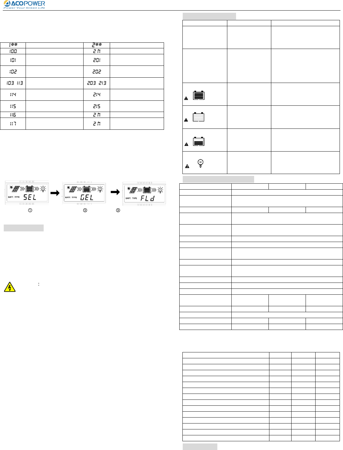
4.3 Load mode setting
Operating Steps:
Under load mode setting interface, press SET button and hold on 5s till the number
begin flashing, then press MENU button to set the parameter, press SET button to
confirm.
Timer 1
Timer 2
Light ON/OFF
Disabled
Load will be on for 1 hour
since sunset
Load will be on for 1 hour
before sunrise
Load will be on for 2 hours
since sunset
Load will be on for 2 hours
before sunrise
~
Load will be on for 3~13
hours since sunset
~
Load will be on for 3~13
hours before sunrise
Load will be on for 14 hours
since sunset
Load will be on for 14
hours before sunrise
Load will be on for 15 hours
since sunset
Load will be on for 15
hours before sunrise
Test mode
Disabled
Manual mode(Default load
ON)
Disabled
NOTE: Please set Light ON/OFF, Test mode and Manual mode via Timer1. Timer2
will be disabled and display "2 n".
4.4 Battery Type
Operating Steps
Under Battery Voltage interface, press SET button and hold on 5s then enter into the
interface of Battery type setting. After choosing the battery type by pressing MENU
button, waiting for 5s or pressing SET button again to modify successfully.
Battery Type
①Sealed (Default) ②Gel ③Flooded
NOTE: Please refer to the battery voltage parameters table for the different
battery type.
5. Protections
PV Short Circuit
When PV short circuit occurs, the controller will stop charging. Clear it to resume normal
operation.
PV Reverse Polarity
Fully protection against PV reverse polarity, correct the wire connection to resume
normal operation.
Battery Reverse Polarity
Fully protection against battery reverse polarity, correct the wire connection to resume
normal operation.
Warning:
Shock Hazard!
When the battery is reverse, the load will appear the equal and reverse
polarity voltage to battery.
Battery Over Voltage
When the battery voltage reaches to the set point of Over Voltage Disconnect Voltage,
the controller will stop charging the battery to protect the battery from being over
charged to break down.
Battery Over Discharge
When the battery voltage reaches to the set point of Low Voltage Disconnect Voltage,
the controller will stop discharging the battery to protect the battery from being over
discharged.
Battery Overheating
The controller detect the battery temperature through the external temperature sensor. If
the battery temperature exceeds 65ºC, the controller will automatically start the
overheating protection to
stop working and recover below 50 ºC.
Load Overload
Load will be switched off when 1.05 times rated current overload happens. Controller
will automatically attempt to reconnect load for 5 times. If overload protection still exist
after controller’s 5 times attempts, user have to reduce load appliance, then press the
SET button or repower the controller or wait for one night-day cycle (night time>3
hours).
Load Short Circuit
Load will be switched off when load short circuit (≥4 times rated current) happens.
Controller will automatically attempt to reconnect load for 5 times. If short circuit
protection still exist after controller’s 5 times attempts, user have to clear short
circuit ,then press the SET button or disconnect and restart the controller or wait for one
night-day cycle (night time>3 hours).
Damaged Remote Tempera
ture Sensor
If the temperature sensor is short-circuited or damaged, the controller will be charging or
discharging at the default temperature 25℃ to prevent the battery damaged from
overcharging or over discharged.
Controller Overheating
If the temperature of the controller heat sinks exceeds 85℃, the controller will
automatically start the overheating protection and recover below 75℃.
High Voltage Transients
PV is protected against small high voltage surge. In lightning prone areas, additional
external suppression is recommended.
6. Troubleshooting
Faults
Possible reasons
Troubleshooting
The LCD is off
during daytime when
sunshine falls on PV
modules properly
PV array
disconnection
Confirm that PV wire connections
are correct and tight
Wire connection is
correct, LCD not
display
1. Battery voltage is
lower than 9V
2. PV voltage is less
than battery voltage
1. Please check the voltage of
battery. At least 9V voltage to
activate the controller
2. Check the PV input voltage
which should be higher than
battery’s
Interface
blink
Battery over voltage
Check if the battery voltage is
higher than OVD point (over
voltage disconnect voltage), and
disconnect the PV.
Interface
blink
Battery
over discharged
When the battery voltage is
restored to or above LVR point
(low voltage reconnect voltage),
the load will recover
Interface
blink
Battery Overheating
The controller will automatically
turn the system off. But while the
temperature decline to be below
50 ºC, the controller will resume.
Interface
blink
Over load or Short
circuit
Please reduce the number of
electric equipments or check
carefully loads connection.
7. Technical Specifications
Item
VS1024A
VS2024A
VS3024A
Nominal system voltage
12/24VDC Auto
Battery input voltage
range
9~32V
Rated charge current
10A
20A
30A
Max. PV open circuit
voltage
50V
Temperature
compensation coefficient
-3mV/℃/2V(25℃)
Self-consumption
≤8.1mA(12V);≤6.5mA(24V)
Charge circuit voltage drop
≤0.29V
Discharge circuit voltage
drop
≤0.16V
LCD temperature range
-20℃~+55℃
Working environment
temperature
-25℃~+55℃*
Humidity range
≤95% (N.C.)
Enclosure
IP30
Grounding
Common Positive
Overall dimension
132x84.6
x39.7mm
149x94.1
x46.1mm
177.5x106.6
x46.2mm
Mounting dimension
120x56mm
137x60mm
165.5x70mm
Mounting hole size
Φ4.5mm
Terminals
4mm
2
16mm
2
16mm
2
Net weight
0.18kg
0.26kg
0.33kg
* If the controller is working under high temperature environment, please derate
capacity in service
Battery Voltage Parameters (parameters is in 12V system at 25℃, please use double
value in 24V.)
Battery charging setting
Sealed
Gel
Flooded
Over Voltage Disconnect Voltage
16.0V
16.0V
16.0V
Charging Limit Voltage
15.0V
15.0V
15.0V
Over Voltage Reconnect Voltage
15.0V
15.0V
15.0V
Equalize Charging Voltage
14.6V
——
14.8V
Boost Charging Voltage
14.4V
14.2V
14.6V
Float Charging Voltage
13.8V
13.8V
13.8V
Boost Reconnect Charging Voltage
13.2V
13.2V
13.2V
Low Voltage Reconnect Voltage
12.6V
12.6V
12.6V
Under Voltage Warning Reconnect Voltage
12.2V
12.2V
12.2V
Under Volt. Warning Volt.
12.0V
12.0V
12.0V
Low Volt. Disconnect Volt.
11.1V
11.1V
11.1V
Discharging Limit Voltage
10.6V
10.6V
10.6V
Equalize Duration
120min
——
120min
Boost Duration
120min
120min
120min
8. Disclaimer
1) Damage from improper use or use in an unsuitable environment.
2) PV or load current, voltage or power exceeding the rated value of controller.
3) User disassembly or attempted repair the controller without permission.
4) The controller is damaged due to natural elements such as lighting.
5)
The controller is damaged during transportation and shipment.
Any changes without prior notice! Version number:V1.0
Add:4120 Valley Blvd, Ste B, Walnut, CA 91789 Tel:1+ 626-575 7722 Wbe:www.acopower.com