EPSOLAR ViewStar series —— Solar Charge Controller OPERATION MANUAL Thank you very much for selecting our product! This manual offers important information and suggestions with respect to installation, use and troubleshooting, etc. Please read this manual carefully before using the product and pay attention to the safety recommendations in it.
ViewStar Star —— Solar Charge Controller Nominal system voltage 12V∕24V∕36V∕48V Nominal charge / discharge current 10A∕20A∕30A∕45A∕60A Final interpretation right of the manual belongs to EPsolar.
Contents 1 Important Safety Information ....................................................................................... 1 2 General Information..................................................................................................... 2 2.1 Product Overview ........................................................................................... 2 2.2 Product Features .............................................................................................. 4 2.
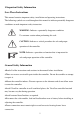
1 Important Safety Information Save These Instructions This manual contains important safety, installation and operating instructions. The following symbols are used throughout this manual to indicate potentially dangerous conditions or mark important safety instruction. WARNING: Indicates a potentially dangerous condition. Use extreme caution when performing this task. CAUTION: Indicates a critical procedure for safe and proper operation of the controller.
2 General Information Thank you for selecting ViewStar series solar charge controller. The controller adopts advanced digital control technology, LCD display and automatical operation. With the features of Pulse Width Modulation (PWM) battery charging and unique control technology, the controller will improve the long battery life efficiently. Our controller has many unique features and easy to use. 2.
Actual Power Display and record function make convenience to check the datum every day, every month and every year RS-485 ports via the open standard Modbus protocol are supported for long-distance communication and communication compatibility Standard RJ45 interface is used to connect to remote display unit (MT50) or PC software to monitor the actual data or modify parameters New SOC method could calculate the battery capacity accurately Electronic protection: Overheating, over discharging, overload,
2.
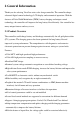
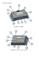
1 – Local temperature sensor It is used to acquire ambient temperature to do temperature compensation for charging and discharging.
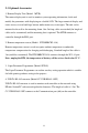
2.3 Optional Accessories 1. Remote Display Unit (Model:MT50) The remote display unit is used to monitor system operating information, faults and modify the parameters with displaying on a backlit LCD. The large numerical display and icons are easy to read and large buttons make menus easy to navigate. The unit can be mounted in the wall or the mounting frame. One 2m long cable are attached (the length of cable can be customized) and the mounting box is optional.
3 Installation Instructions 3.1 Mounting Read through the entire installation section first before beginning installation. Be very careful when working with batteries. Wear eye protection. Have fresh water available to wash and clean any contact with battery acid. Uses insulated tools and avoid placing metal objects near the batteries. Explosive battery gasses may be present during charging. So well ventilation of battery box is recommended.
Step 1: Choose Mounting Location Locate the controller on a vertical surface protected from direct sun, high temperature, and water. And make sure good ventilation. Step 2: Check for clearance Place the controller in the location where it will be mounted. Verify sufficient room to run wires and sufficient room above and below the controller for air flow. 150mm(5.9inches) Warm air 150mm(5.9inches) Cool air Step 3: Mark Holes Mark the four (4) mounting hole locations on the mounting surface.
3.2 Wiring NOTE: A recommended connection order has been provided for maximum safety during installation. NOTE: the controller is common negative one. CAUTION: Don’t connect the loads with surge power exceeding the ratings. CAUTION: Secure all wiring for mobile applications. Use cable clamps to prevent cables from swaying. Unsecured cables create loose and resistive connections which may lead to excessive heating and/or fire.
on automatically. Controller’s load terminals can be connected to DC electric equipments whose nominal operation voltage is the same as nominal voltage of battery. The controller supplies power to loads with battery voltage. It is suggested that positive pole or negative pole of battery and loads be connected to a safety device whose operation current is not twice lower than nominal charging or discharging current. Do not switch on the safety device while it is being installed.
Step 1: Wiring and switching on After solar system is wired, check all wirings carefully to make it clear whether all 6 terminals are connected correctly and tightened. According to the order of switching on in the chart, battery first, loads second and solar module third successively to avoid nominal system voltage identification error.
4 Operation 4.1 PWM Technology (Series Pulse Width Modulation) The controller adopts the advanced series pulse width modulation (PWM) charging mode. With range of 0-100%, it can charge the battery quickly and stably under any condition of solar photovoltaic system. PWM charging mode use automatic conversion duty ratio pulses current to charge the battery. The battery can be fully charged safety and rapidly with the pulse current.
is used to prevent heating and excessive battery gassing. The Boost stage remains 120 minutes and then goes to Float Charge. Every time when the controller is powered on, if it detects neither over discharged nor overvoltage, the charging will enter into boost charging stage. · Float Charge After the battery is fully charged in Boost voltage stage, the controller reduces the battery voltage to Float voltage set point.
Equalize Charge WARNING: Risk of explosion! Equalizing flooded battery can produce explosive gases, so well ventilation of battery box is necessary. NOTE: Equipment damage! Equalization may increase battery voltage to the level damaging to sensitive DC loads. Ensure that all load allowable input voltages are greater than the equalizing charging set point voltage. NOTE: Equipment damage! Over-charging and excessive gas precipitation may damage the battery plates and activate material shedding on them.
4.3 HMI Interface Charging indicator Fault indicator LCD WELCOME V2.35+V2.63 ! MENU/← ↑/ + ↓/ - ENTER/→ ■ Buttons instruction: Cursor down / Number reduce button Cursor up / Number add button Menu / Cursor left button Enter / cursor right button Charging indicator GREEN ON whenever sunlight is available for battery charging and the charging system is normal.
Fault indicator When the following cases occur, fault indicator red flashing: Solar module: Over current, Measure error of voltage, Short of reverse-protection MOS-I, Short of charging MOS-C, MOS-I or MOS-C disconnection or MOS break in control section; Battery: Over voltage, Measure error of voltage, Over temp; Load: Over load, Short, Short of discharging MOS, Measure error of voltage; Device: Over temperature. For trouble shooting, refer to chapter 5.
4.4 Operation and Displaying Load mode 1.Manual mode(default) This mode is to turn ON and OFF the load by press Parameter button. Detail Note The load will open automatically Press ENTER button to after the controller is initialized.
3. Light ON + Timer When solar module voltage goes below the point of NTTV (Night Time Threshold Voltage) at sunset; the solar controller will recognize the starting voltage and turn on the load after pre-set delay time. Working time 2 is the open time of load in the light mode before dawn. The load will be on for several hours which users set. If the work time are changed during the process, the controller will not reset the counter.
Parameter Detail Note Working The open time of load in the light mode The value is set to ZERO after dusk means the controller will The open time of load in the light mode not work at this working before dawn time period; the actual The controller calculated the total time of load-on is relative length of the night by self-learning. The with night time, working time should be more than 3 hours time1 and working time2 Time 1 Working Time 2 Night time 4.
● Battery Charging Setting Battery Type Note Sealed (default) GEL flooded Constant value Constant value Constant value User Defined by user 20
Operation and displaying of controller Initialization Interface When controller is powered on, the following picture will be painted during the initialization: WELCOME V2.36 + V2.63 Main Menu Interface After controller is initialized, the monitoring interface will update automatically.
System Monitor Interface In the main menu interface, press or , the inverse cursor moves between main menu 1 and main menu 2.When the inverse cursor points at 1.Monitoring in the main menu 1, press to enter into the system monitoring interface which displays contents as below. Press or t display every real-time parameters interface circularly. ▼Solar array voltage and current The interface shows real-time voltage and current of solar module. PV 14.5V 7.
TEMP 25.6 °C SOC: 47% ▼ Load voltage and current Press and enter into the following interface which indicates actual voltage and current of loads. LOAD 12.5V 5.5A ▼ Real-time clock and imaging system status Press and enter into the following interface which indicates real-time clock and graphic system status. If choose the manual mode with loads, press the interface to control loads on and off alternatively.
■ Introductions to system status icons: :Day :Night :Charging :Normal :LVD :Normal :UVW :LVD :ON :OFF ﹡ Icons indicating battery charging are dynamic effects. ▼ System status Press and enter into the following interface which indicates system status.
PV status: Connect Disconnect Measure Err MOS-I Short MOS-C Short MOS Break BATT charging status: Equalize Boost Float No Charge BATT status: LVD UVW Normal OVD Error OverTemp LOAD status: On Off Short Error OverLoad MOS Short DEVICE status: Normal OverTemp ﹡ When fault with inverse cursor above exists for 2 minutes along without any operation, it will jump into that page automatically. ▼ Charging energy statistics Char. Energy Day: 1.17KWh Mon: 25.35KWh Total: 98.
▼ Discharging energy statistics Disch. Energy Day: 0.75KWh Mon: 18.53KWh Total: 54.32KWh Device Setting In the main menu, press or point to 2.Device Set, press button to make the inverse cursor to enter device setting interface which displays the following contents. When setting in this interface, real time clock will stop running. Please correct real time clock again after parameters are changed.
Save Parameters Save Cancel If save confirmation is chosen, the system will automatically check the validity of parameters. If the check is passed, the promptation of successful saving will occur below. After parameters successfully saved, it returns to main menu interface. SAVE SUCCESS! Press and hold both and button for 3 seconds to enter factory mode in the main interface. The authority code to clear Energy Log is 102206 as default.
Charging and Discharging Parameters Setting Interface press to enter into charging and discharging parameters setting interface as inverse cursor at 3.Parameter Set in main menu 1. press , it moves back to the previous interface and the inverse cursor points to the position of the first parameter.
▼ Control parameters interface 1 Press continuously and the inverse cursor will move to the control parameters interface. Press or to modify the following control parameters. The value in this interface could be modified only when the battery type is USER defined. Parameter Set Over Volt. Disc : 16.0V Charg Lmt : 15.5V Over Volt. Rect : 15.0V ▼ Control parameters interface 2 Press continuously and the inverse cursor will move to the control parameters interface.
▼ Control parameters interface 3 Press continuously and the inverse cursor will move to the control parameters interface. Press or to modify the following control parameters. The value in this interface could be modified only when the battery type is USER defined. Parameter Set Boost V. Rect : 13.2V Under V. Rect :12.2V Under V. Warn:12.0V ▼ Control parameters interface 4 Press continuously and the inverse cursor will move to the control parameters interface.
▼ Control parameters interface 5 Press continuously and the inverse cursor will move to the control parameters interface. Press or to modify the following control parameters. Parameter Set Equa.Time : 120Min BoostTime : 120Min Range from 0 to 180 Range from 10 to 180 The interface below will prompt only when the SOC is selected in the Batt Mng Mode.
When save operation confirmed, the indication of successful saving will prompt as follows. After parameters successfully saved, it returns to main menu interface. Parameter Set Under V. Warn : 12.0V SAVE SUCCESS! Low V. Disc : 11.1V Discharg Lmt : 10.8V Load Control Interface When the inverse cursor rests on 4.Load Set in main menu 1, press and enter load control interface with the following contents displayed.
Manual Default ON OFF Press or press and the messagebox below will prompt. When it is cancelled, the to choose ON or OFF as default. After confirmation, inverse cursor moves back to the main menu interface. Manual Default Save ON Cancel OFF When save confirmation chosen, the indication of successful saving will occur as follows. After parameters successfully saved, it returns to main menu interface.
Light Press sequencely. Press On/Off On : 05.0 V Delay :10 m Off : 06.0 V Delay :10 m or , the inverse cursor moves among each parameters or to modify the values. The below message box will be prompted after press Enter. Press or to choose save or cancel operation. When modification canceled, the interface will go back main menu. Light On/Off On : 06.0 V Save Delay :10 m Cancel Off : 05.
Light On + Timer On : 05.0 V Delay :10 m Off : 06.0 V Delay :10 m Night Time : 10 : 00 Light On + Timer Press or Period 1: 01:00 Period 2: 01:00 to modify each parameter. The below message box will be prompted after press save or cancel operation. When . Press or to choose modification canceled, the interface will go back main menu. Light On + Timer Save Cancel Work Time : 10 : 00 : 00 When save operation confirmed, the indication of successful saving will prompt as follows.
Light On + Timer On : 06.0 V Delay :10 m SAVE SUCCESS! Off : 05.0 V Delay :10 m Work Time : 10 : 00 : 00 NOTE: When the “OFF” time is later than local sunrise time, the controller will turn off the load output at the sunrise time, because light control’s priority level is higher! ▼ Time control interface When the inverse cursor rests on Time in the time control interface, press enter into time control interface. Press or to to modify all parameters of time interval 1.
Time Control 2 On Time : 16 : 30 : 00 Off Time : 06 : 00 : 00 Single Double * In the double time control mode, time1 and time2could not overlap. When choosing Single, only value of time1 can be modified.
When updating successfully, the prompt will show below and then move back to the main menu. Time Control 2 On Time : 19 : 20 : 00 SAVE SUCCESS! Off Time : 07 : 00 : 00 Single Double Nominal Parameter Interface press or , move inverse cursor to 5.Rated Value, then press button to enter into nominal parameter interface below. Battery rate and capacity can be modified. the batter rate are 12v, 24v, 36v, 48v or auto. Battery capacity ranges from 1 to 9999AH in the interface,.
Rated Value Batt : 12.0 V Save Cancel Load : 10.0A PV : 10.0A Type : Seal Gel Flood When updating successfully, the prompt will show below and then move back to the main menu. Rated Value Batt : 12.0 V SAVE SUCCESS! Load : 10.0A PV : 10.
Password Ori. PSW: 000000 New PSW: 000000 If changing the value, press prompt: Press to submit and the following message will to select ―save‖ to confirm update or cancel. or After confirmed, the cursor will move back to the main menu. Time Control 2 Save Parameters On Time : 19 : 20 : 00 Cancel OffSave Time : 07 : 00 : 00 Double Single When updating successfully, the prompt will show below and then move back to the main menu.
Battery Charge Mode Setting Interface Press or press and enter into test mode interface below: , move inverse cursor to 8.Batt Mng Mode, then Batt Mng Mode V.C. If changing the value, press prompt: Press SOC to submit and the following message will to select ―save‖ to confirm update or cancel. or After confirmed, the cursor will move back to the main menu.
Factory Reset Mode Interface Press or , move inverse cursor to 9.Factory Reset , then press and enter into test mode interface below: Factory Reset NO If changing the value, press prompt: Press YES to submit and the following message will to select ―save‖ to confirm update or cancel. or After confirmed, the cursor will move back to the main menu. Factory Reset OK Cancel NO YES When updating successfully, the prompt will show below and then move back to the main menu.
Reboot Device Setting Interface Press or press and enter into test mode interface below: , move inverse cursor to 10.Reboot Device , then Reboot Device No Yes If needing to reboot the device, press to submit and the device will reboot at once. 4.5 remote communication and monitor With special communicate cable, user could monitor the status and modify the parameters.
3- PC monitor software(need one private usb to rs485 cable, model: CC-USB-RS485-150U) WARNING: Do not use the standard twisted-net cable to connect the device and PC net interface, or the permanent damage will occur.
5 Protection, Troubleshooting and Maintenance 5.1 Protection • PV Array Short Circuit If PV array short circuit occurs, clear it to resume normal charge automatically. • Load Overload If the load current exceeds the rated current of controller(≥1.05 times rated discharge current), the controller will disconnect the load. Overloading must be cleared up, then pressing the switch button. • Load Short Circuit Fully protected against load wiring short-circuit(≥2 times rated discharge current).
• High Voltage Transients PV is protected against smaller high voltage surge. In lightning prone areas, additional external suppression is recommended. Note: The controller has daily automatic fault recovery function which will reduce the manual operation and can intelligently eliminate the fault caused by non-actual hardware failure. 5.
Charging and discharging Battery voltage circuit is off and monitor sensor shows Error. abnormal Please restart controller, if the fault is still exists, cut off charging and discharging circuit immediately and contact the supplier to make maintenance. Discharging circuit is off Load power and monitor shows Over surpasses nominal Please reduce the number of electric Load. power equipments. When load power reaches 1.05-1.25 times, 1.25-1.5 times and 1.
Discharging circuit is off Load and the LOAD monitor short circuit is Please check carefully loads shows Short. connection; It is reactivated after delayed 5 seconds for the first time, 10 seconds for the second time, 15 seconds for the third time, 20 seconds for the fourth time and 25 seconds for the fifth time. If over 5 times, push the ENTER key and controller recover output after 10 seconds.
5.3 Maintenance The following inspections and maintenance tasks are recommended at least two times per year for best performance. Check that the air flow and ventilation around the controller is not blocked. Clear all dirt or fragments on the heat sink. Check all the naked wires to make sure insulation is not damaged for serious solarization, frictional wear, dryness, insects or rats etc. Maintain or replace the wires if necessary. Check and confirm that LED or LCD is consistent with required.
6 Technical specifications Model: VS****BN 1024 2024 3024 4524 6024 Electrical Parameters Nominal System 12V ∕ 24V Auto recognized Voltage Maximum Battery 32V Voltage Maximum PV Voltage 48V Rated Battery Current (A) 10 20 30 Charge Circuit Voltage 45 60 ≤0.69V Drop Discharge Circuit ≤0.17V Voltage Drop ≤15mA@12v; ≤13mA@24v Self-consumption Communication RS485 / RJ45 interface Remote temperature 2ERJ—3.
Model: VS****BN 2048 3048 4548 6048 Electrical Parameters Nominal System 12V ∕ 24V ∕ 36V ∕ 48V Auto recognized Voltage Maximum Battery 64V Voltage Maximum PV Voltage Rated Battery Current (A) 96V 20 30 Charge Circuit Voltage 45 60 ≤0.53V Drop Discharge Circuit ≤0.16V Voltage Drop ≤15mA@12v; ≤10mA@24v; Self-consumption ≤9mA@36v; ≤8mA@48v; Communication RS485 / RJ45 interface Remote temperature 2ERJ—3.
Battery Control Parameters All the coefficient is referred to 25℃, and twice in 24v system rate, triple in 36v system rate and quadruple in 48v system rate. Battery Type Gel Sealed Flooded User High Volt Disconnect 16V 16V 16V 9~17V Charging limit voltage 15V 15V 15V 9~17V Over Voltage Reconnect 15V 15V 15V 9~17V Equalization voltage —— 14.6V 14.8V 9~17V Boost voltage 14.2V 14.4V 14.6V 9~17V Float voltage 13.8V 13.8V 13.8V 9~17V Boost return voltage 13.2V 13.2V 13.
Threshold voltage value Night Time Threshold Voltage Day Time Threshold Voltage Upper limit 10V;20V∕24V; 30V∕36V; 40V∕48V Low limit 1V; 2V∕24V; 3V∕36V;4V∕48V Default 6V/12V Upper limit 10V; 20V∕24V;30V∕36V; 40V∕48V Low limit 1V; 2V∕24V; 3V∕36V;4V∕48V Default 5V/12V Temperature compensate Temperature Upper limit 0mV∕℃∕2V compensate Low limit -9mV∕℃∕2V coefficient Default -3mV∕℃∕2V @25℃ * Compensation of equalize, boost, float and low voltage disconnect voltage.
39.5 85 55 Φ4.5 150 162 Dimensions 49.5 VS1024BN 150 162 VS2024BN Dimensions 100 70 Φ4.
57.7 70 103 Φ4.2 191 200 Dimensions 58.6 VS2048BN & VS3024BN 191 200.6 VS3048BN & VS4524BN Dimensions 109 80 Φ4.
66.6 119 80 Φ4.5 195 204.8 Dimensions 67 VS4548BN 195 204.8 VS6024BN Dimensions 129 90 Φ4.
185 64 205 195 130 Φ5 VS6048BN Dimensions 174
Version number: V1.
BEIJING EPSOLAR TECHNOLOGY CO., LTD. Tel:010-82894112 / 82894962 Fax:010-82894882 E-mail:info@epsolarpv.com Website: www.epsolarpv.