iTracer-ND series ——MPPT Solar Charge Controller User Manual Models: IT4415ND/IT6415ND
Important Safety Instructions Please reserve this manual for future review. This manual contains all instructions of safety, installation and operation for Maximum Power Point Tracking (MPPT) controller in iTracer-ND series ("the controller" is referred in this manual). General Safety Information Read carefully all the instructions and warnings in the manual before installation. No user serviceable component inside controller. DO NOT disassemble or attempt to repair the controller.
Contents 1 General Information .......................................................................................1 1.1 Overview .............................................................................................1 1.2 Characteristics.....................................................................................2 1.3 Accessories Instructions ......................................................................4 1.4 Maximum Power Point Tracking Technology .................................
1 General Information 1.1 Overview Appreciate you for choosing our MPPT solar charge controller, iTracer-ND series. Based on multiphase synchronous rectification technology (MSRT) and common negative design, with dual-core processor architecture and advanced MPPT control algorithm, the products in this series have the features of high response speed, high reliability, high industrial standards, etc.
12/24/36/48VDC automatically identifying system voltage or user-defined working voltage. Concise human-computer interactive interface, convenient multiple combination keys, dynamically displaying system operating data and working condition. Multiple load control modes: manual control, light ON/OFF, light on+timer and time control. Support 4 charging options: Sealed, Gel, Flooded and User. Battery temperature compensation function. Real-time energy statistics function.
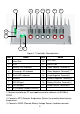
11 12 2 14 13 15 16 17 10 9 7 8 Figure 1-1 Controller Characteristics Item Name Item Name ② 1 Heat Sink 10 RTS Port 2 LCD 11 RBVS Port 3 Battery LED indicator 12 Solar Positive Terminal(+) 4 Charging LED indicator 13 Solar Negative Terminal(-) 5 Fault LED indicator 14 Load Negative Terminal(-) 6 Buttons 15 Battery Negative Terminal(-) 7 RS-232 port 16 Battery Positive Terminal(+) 17 Load Positive Terminal(+) ① 8 RS-485 port 9 RTC battery (model:CR2032) ③ ④
battery voltage. ④ The PV negative, battery negative and load negative is common. 1.3 Accessories Instructions 1. Remote Temperature Sensor (Model: RTS300R10K5.08A) Acquisition of battery temperature for undertaking temperature compensation of control parameters, the standard length of the cable is 3m (length can be customized). The RTS300R10K5.08A connects to the RTS th port (10 ) on the controller. NOTE:Unplug the RTS, the temperature of battery will be set to a fixed value 25℃. 2.
technology will boost the battery charge current through tracking the MPP. Assuming 100% conversion efficiency of the solar system, in that way, the following formula is established: Input power (PPV)= Output power (PBat) Input voltage (VMp) *input current (IPV) =Battery voltage (VBat) *battery current (IBat) Normally, the VMp is always higher than VBat, Due to the principle of conservation of energy , the IBat is always higher than IPV.
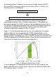
Figure 1-3 Mutil-MPP Curve If the program works improperly after appearing Multi-MPP, the system will not work on the real max. power point, which may waste most solar energy resources and seriously affect the normal operation of the system. The typical MPPT algorithm, designed by our company, can track the real MPP quickly and accurately, improve the utilization rate of the array and avoid the waste of resources. 1.
A) Bulk Charging In this stage, the battery voltage has not yet reached constant voltage (Equalize or Boost Voltage), the controller operates in constant current mode, delivering its maximum current to the batteries (MPPT Charging).
ATTENTION: Dégât sur l'équipement! Un chargement excessif et une précipitation de gaz peut endommager les plaques de la batterie et la formation de matières actives dessus. Un chargement trop fort ou une égalisation prolongée peut causer des dégâts. Inspectez soigneusement les conditions spécifiques de la batterie utilisée dans le système. Some types of batteries benefit from equalizing charge on a regular basis, which is able to stir electrolyte, balance battery voltage and accomplish chemical reaction.
2 Installation 2.1 General Installation Notes Before installation, please read through the entire installation instructions to get familiar with the installation steps. Be very careful when installing the batteries, especially flooded lead-acid battery. Please wear eye protection, and have fresh water available to wash and clean any contact with battery acid. Keep the battery away from any metal objects, which may cause short circuit of the battery.
point voltage (Vmpp) of the MPPT controller, the series number of different types PV modules can be calculated. The below table is for reference only. 36cell 48cell 54cell 60cell System Voc<23V Voc<31V Voc<34V Voc<38V voltage MAX. Best MAX. Best MAX. Best MAX. Best 12V 24V 48V 4 6 6 2 3 5 2 4 4 2 4 4 1 2 3 2 3 3 1 2 3 Thin-Film Module MAX. Best MAX.
When the PV array straight polarity, the actual operation of the PV array must NOT exceed three times of rated charge power;When the PV array reverse polarity, the actual operation must NOT exceed 1.5 times. For real application please refer to the table below: Model Rated Charge Current Rated Charge Power Max.
Figure 2-1 Installation Diagram 150mm of clearance is required around the controller for proper air flow. Secure the controller in place using proper mounting screws. 2.4 Wiring ※Please remove the terminal protective cover before wiring.
CAUTION: The following connection order is recommended for optimal safety. CAUTION: Do not entangle all wiring together. Communication cable and power wires should be as far as possible to avoid interfering communication signal transmission. CAUTION: The iTracer-ND controller is a negative ground controller. Any negative connection of PV, load or battery can be earth grounded as required. CAUTION: For mobile applications, be very certain that all wirings are connected securely.
ATTENTION: Le contrôleur procédera à une compensation de température pour les paramètres de chargement en fonction de la température de l'appareil. AVERTISSEMENT : Dégât sur l'équipement! Ne placez jamais le capteur de température dans une batterie. Le RTS300R10K5.08A aussi bien que la batterie seront endommagés. The included remote temperature sensor (RTS300R10K5.08A )is recommended for effective temperature compensated charging. Connect the th RTS300R10K5.
controller (Check Figure 1-1). A twin-cord cable is recommended but not required. Please be careful to spot the ‗+‘ and ‗-‘ when connecting. No damage will result if the polarity is reversed, but the controller can‘t read a reversed sensor voltage. Plugging the voltage sensor wires into to the RTS300R10K5.08A th terminals (10 Port) will cause an alarm or damage the controller. ③ Communicate Connection WARNING: Shock Hazard! There should not any communication cables and power lines intertwined.
Model Max. PV input current Max.
Figure 2-2 Connection Diagram Battery Connection Connecting a fuse in series through battery positive (+) in the circuit and the battery circuit fuse must be 1.25 to 2 times to the rated current. Keep OFF before connection. Connect battery positive (+) and negative (-) to battery terminals on the controller in the figure 1-1. Please pay much attention to ‗+‘ and ‗-‘. Load Connection Connecting a breaker in series in the load circuit and the breaker must be 1.25 to 2 times of the rated current.
NOTE: Load short circuit protection and the reversed polarity connection will trigger automatically. WARNING: Controller will be damaged when the PV array reverse polarity and the actual operation power of the PV array is 1.5 times greater than the rated charge power! 2.5 Power Up CAUTION: The controller is only powered by battery, so it will not work when connected only to solar input. WARNING: Disconnect the battery will produce interference to the load when the controller is work at charging.
3 LED Indication LED Indication Color Indicator Status Green flash Charging Green OFF No charging Green on solid Green Slowly Flashing Green fast flash High volt disconnect Orange on solid Under voltage warning Red on solid Low voltage disconnect Red flash Battery over temperature Red OFF Normal Normal Full Current abnormal Red flash Charging overcurrent PV overvoltage Overload load short Charging(green) and battery indicator (Red) flashing simultaneously Charging(green) and
4 LCD Display & Operation 4.1 Button operation Button Introduction Enter corresponding interface Save the data Return main menu in any monitoring interface Cancel the operation Move inverse cursor Browse the parameters Modify the value Set the period of log 4.2 LCD Display & Operation Rated Info Rated Para Rat.Volt 48.0V Chrg.Cur 60.0A Disc.Cur 60.0A Rated information of the controller will be displayed. Monitor interface will be switched after 3 seconds.
Main Menu There are 9 interfaces for monitoring, as shown in the below picture. Press button to move inverse cursor among 9 menus. 1.Monitoring 2.Log Info 3.Clock Set 4.Local Para Set 5.Load Set 6.Control Para 7.Sys Password 8.Default Set 9.Load Set Monitor There are 11 interfaces for monitoring, as shown below: Load State ON Local Temp 25.5 ºC Load Volt. 12.4V Load Cur. 2.2A Batt Volt. 12.4V Batt Cur. 2.2A Total Generated 7.50kWh Total Consumed 5.50kWh Batt Day’Max 13.5V Batt Day’Min 11.
Log Info There are two items of log record as shown blew. <1>Work Log <2>Alarm Log Work Log Query From 2012-01-01 To 2012-06-08 Total:79 No. 1/79 2012-01-01 00:00 Batt Volt 13.3V Batt Cur 0.0A <1>Work Log <2>Alarm Log Alarm Log Query From 2012-01-01 To 2012-06-08 Total:10 No. 1/10 Batt OVD/Begin 2012-01-04 14:20 Para 17.20V PV Cur 0.0A Discharging Cur 0.
promoted if adjusted and save operated successfully. Input Password Save Cancel Save success! 000000 NOTE:The log after the current time will be erased when the clock have be adjusted. Device Parameter There are 2 interfaces about device parameter as shown blew: Backlight Time 60 s Storage Interval 10min Local ID T03-0001 You should input the user password (see above) before setting the parameters.
Parameter ON OFF Detail The load will turn on automatically after the controller is initialized. If the battery power is enough and the controller works well, load will keep on. The load will turn off after the controller is initialized. Only when the load turn on manually, load can be output. If the battery power is enough and the controller works well, load will keep on. Light On/Off ◎Manual √ Light On/Off ◎ Light On+Timer ◎ Time Light On/Off On 05.0V T 10 M Off 06.
Parameter Working Time 1 Working Time 2 Night time Detail The work time of load in the light mode after dusk The work time of load in the light mode before dawn The controller calculated the total length of the night by self-learning. The time should be more than 3 hours Time ◎Manual ◎ Light On/Off ◎ Light On+Timer √ Time Time Control 1 On Time 19 : 00 Off Time 02 : 00 Time Control 2 On Time 05 : 00 Off Time 06 : 00 Single Double Load control mode can be set to time control in this interface.
Control Parameter There are 9 interfaces for ‗Control Parameter‘ as shown below. Batt Type SEALED Batt AH 200AH Over Volt. Disc. 16.0V Charge Limit 15.0V Temp Coefficient -3mV/℃/2V Rated Volt AUTO Over Volt. Rect 15.0V Equalize Charge 14.6V Boost Charge 14.4V Float Charge 13.8V Equalize Time 120 min Boost Time 120 min Low Volt Disc 11.1V Discharge Limit 10.6V Under Volt Rect 12.2V Under Volt Warn 12.0V Boost Rect Volt 13.2V Low Volt Rect 12.
Battery Control Parameters All coefficient is referred to 25℃, and twice in 24V system rate, triple in 36Vsystem rate and quadruple in 48Vsystem rate. Battery Type Sealed Gel Flooded User High Volt Disconnect 16V 16V 16V 9~17V Charging limit voltage 15V 15V 15V 9~17V Over Voltage Reconnect 15V 15V 15V 9~17V Equalization voltage 14.6V —— 14.8V 9~17V Boost voltage 14.4V 14.2V 14.6V 9~17V Float voltage 13.8V 13.8V 13.8V 9~17V Boost return voltage 13.2V 13.2V 13.
Password Sys Password Old PSW 000000 New PSW 000000 The factory default password is ―000000”. Default Set Default Set No Yes Clr Log Record Retain clear Press button to enter to restore the default interface and clear all logs including work log and alarm log. NOTE: All parameters will be set to factory default and couldn‘t be recovery. Device Message ARM Msg. Type:IT6415ND Ver:V01.00+V02.60 SN:0002201301200045 Dsp Msg. Type: IT6415ND Ver: V02.05+V02.
5 Protections, Troubleshooting & Maintenance 5.1 Protections PV Over Current The controller will limit charge power in rated charge power. An over-sized PV array will not operate at maximum power point PV Short Circuit If the PV array short circuit, the controller will stop charging, clear it to resume normal operation. PV Reverse Polarity Fully protection against PV reverse polarity, correct the wire connection to resume normal operation.
Load Over Load Load will be switched off when 1.05 times rated current overload happens. Controller will automatically attempt to reconnect load for 5 times. If overload protection still exist after controller‘s 5 times attempts, user have to reduce load appliance, then press the button or repower the controller or wait for one night-day cycle (night time>3 hours) or press button. Load Short Circuit Load will be switched off when load short circuit (≥4 times rated current) happens.
green fast blink and LCD displaying ‗OVD‘ Fault LED indicator blink, LCD displaying ‗Current Err‘ larger than over voltage disconnect voltage (OVD) Charging current in three phases is unbalanced Fault LED indicator blink, LCD displaying ‗Over Volt‘ Solar modular output is too high Fault LED indicator blink, LCD displaying ‗Over Temp‘ Heat sinks operational temperature is quite high to 85 ºC or above Cannot connect to the controller via RS-485 or RS-232 RS-485 serial baud rate setting error or serial-
serious solarization, frictional wear, dryness, insects or rats etc. Repair or replace some wires if necessary. Tighten all the terminals. Inspect for loose, broken, or burnt wire connections. Check and confirm that LED or LCD is consistent with required. Pay attention to any troubleshooting or error indication .Take necessary corrective action. Confirm that all the system components are ground connected tightly and correctly.
6 PC Software The controller can be connected to a common PC monitoring software by supporting USB communication cable developed by the EPsolar company. Monitoring software can remote single or more controllers to modify the parameters and others in the PV system management (username: administrator, password: 111111 as default). See the specific instructions related software user guide.
Figure6-2 Real Time Monitoring Figure6-3 Control Parameter 34
7 Specifications Electrical Parameters Item Nominal System Voltage Nominal Battery Current Battery Input Voltage Range Max. PV open circuit voltage MPP Voltage Range Maximum Input Power IT4415ND IT6415ND 12/24/36/48VDC 45A 60A 8V~68V 150V (at minimum operating environment temperature) 138V (at 25℃ environment temperature) ① Battery voltage+2V~108V 600W/12V;1200W/24V 800W/12V;1600W/24V 1800W/36V;2400W/48V 2400W/36V;3200W/48V 1.4W~2.6W Self Consumption Discharge Circuit Voltage ≤0.
8 Disclaimer Damage from improper use or use in an unsuitable environment. PV or load current, voltage or power exceeding the rated value of controller. User disassembly or attempted repair the controller without permission. The controller is damaged due to natural elements such as lighting. The controller is damaged during transportation and shipment.
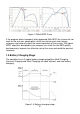
Annex I Conversion Efficiency Curves Illumination Intensity: 1000W/m 2 Temperature: 25℃ Test model: IT4415ND 1.Solar MPPT Voltage(36V, 54V, 72V) / System Voltage(12V) 12V Conversion Efficiency Curves 97.50% Conversion Efficiency % 95.50% 93.50% 36V 91.50% 54V 89.50% 72V 87.50% 120 180 210 270 300 330 390 480 520 600 Charging Power W 2.Solar MPPT Voltage(36V, 54V, 72V) / System Voltage(24V) 24V Conversion Efficiency Curves 99.00% Conversion Efficiency % 98.00% 97.00% 96.00% 95.00% 36V 94.
3.Solar MPPT Voltage(54V, 72V, 90V) / System Voltage(36V) 36V Conversion Efficiency Curves Conversion Efficiency % 99.00% 98.00% 97.00% 96.00% 95.00% 94.00% 93.00% 92.00% 91.00% 54V 72V 90V 130 390 650 780 910 1040 1300 1560 1690 1800 Charging Power W 4.Solar MPPT Voltage(72V, 90V, 108V) / System Voltage(48V) 48V Conversion Efficiency Curves 99.00% Conversion Efficiency % 98.00% 97.00% 96.00% 95.00% 72V 94.00% 90V 93.00% 108V 92.
Test model: IT6415ND 1. Solar MPPT Voltage(36V,54V, 72V) / System Voltage(12V) 12V Conversion Efficiency Curves Conversion Efficiency % 97.00% 96.00% 95.00% 94.00% 93.00% 92.00% 91.00% 90.00% 89.00% 36V 54V 72V 150 180 210 240 270 300 330 390 480 520 650 780 Charging Power W 2. Solar MPPT Voltage(36V, 54V, 72V) / System Voltage(24V) 24V Conversion Efficiency Curves 99.00% Conversion Efficiency % 98.00% 97.00% 96.00% 95.00% 36V 94.00% 54V 93.00% 72V 92.
3. Solar MPPT Voltage(54V, 72V, 90V) / System Voltage(36V) 36V Conversion Efficiency Curves Conversion Efficiency % 99.00% 98.00% 97.00% 96.00% 95.00% 94.00% 93.00% 92.00% 91.00% 54V 72V 90V Charging Power W 4. Solar MPPT Voltage(72V, 90V, 108V) / System Voltage(48V) 48V Conversion Efficiency Curves 99.00% Conversion Efficiency % 98.50% 98.00% 97.50% 97.00% 72V 96.50% 90V 96.00% 108V 95.
Annex II Dimensions IT4415ND Dimensions(Unit:mm) 41
IT6415ND Dimensions(Unit:mm) Final interpretation right of the manual belongs to EPsolar. Any changes without prior notice! Version number:V3.
BEIJING EPSOLAR TECHNOLOGY CO., LTD. Tel: +86-10-82894112 / 82894962 Fax: +86-10-82894882 E-mail:info@epsolarpv.com Website: http://www.epsolarpv.com/ http://www.epever.