
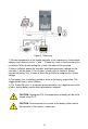
User Manual

10
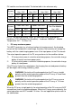
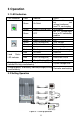
Model
Rated Charge
Current
Rated Charge
Power
Max. PV Array
Power
Max. PV open
circuit voltage
Tracer1215BN
10A
130W/12V
260W/24V
390W/12V
780W/24V
150V
①
138V
②
Tracer2215BN
20A
260W/12V
520W/24V
780W/12V
1560W/24V
Tracer3215BN
30A
390W/12V
780W/24V
1170W/12V
2340W/24V
Tracer4215BN
40A
520W/12V
1040W/24V
1560W/12V
3120W/24V
①At minimum operating environment temperature
②At 25℃ environment temperature
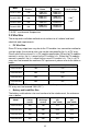
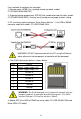
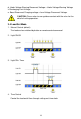
2.3 Wire Size
The wiring and installation methods must conform to all national and local
electrical code requirements.
PV Wire Size
Since PV array output can vary due to the PV module size, connection method or
sunlight angle, the minimum wire size can be calculated by the I
SC
of PV array.
Please refer to the value of I
SC
in PV module specification. When the PV modules
connect in series, the I
SC
is equal to the PV module‘s I
SC
. When the PV modules
connect in parallel, the I
SC
is equal to the sum of PV module‘s I
SC
. The I
SC
of PV
array must not exceed the maximum PV input current, please refer to the table as
below:
Model
Max. PV input current
Max. PV wire size (mm
2
/AWG)
Tracer1215BN
10A
4/12
Tracer2215BN
20A
6/10
Tracer3215BN
30A
10/8
Tracer4215BN
40A
16/6
NOTE: When the PV modules connect in series, the open circuit voltage of the
PV array must not exceed 138V (25℃).
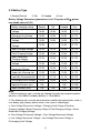
Battery and Load Wire Size
The battery and load wire size must conform to the rated current, the reference
size as below:
Model
Rated
charge
current
Rated
discharge
current
Battery wire
size
(mm
2
/AWG)
Load wire
size
(mm
2
/AWG)
Tracer1215BN
10A
10A
4/12
4/12
Tracer2215BN
20A
20A
6/10
6/10
Tracer3215BN
30A
20A
10/8
6/10
Tracer4215BN
40A
20A
16/6
6/10