
Design) User guide
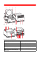
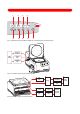
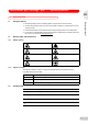
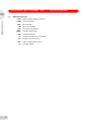
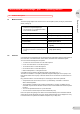
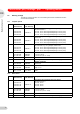

Abb. 1: Fig. A: Front and rear view of the com plete system with gel dryer connection
Fig. A: Front and rear view of the complete system with gel dryer connection
Abb. 2: Fig. B: Fron t and rear view of the basic device
Fig. B: Front and rear view of the basic device
1 Pump outlet (complete system) 2 Lid made from PMMA
3 Sealing ring 4 Grip recess
5 Emergency release 6 Pump housing (complete system)
7 Name plate 8 Mains connection
9 Fuse holder 10 Mains power switch
11 Operating controls and device display 12 Emission condenser (complete system)
13 Gel dryer connection (complete system) 14 Pump connection (basic device)
15 Mains connection for external vacuum pump
(basic device)
12 3
45
6
7
8
9
10111213
2
3
4
5
14
15910711 8