ii Copyright Copyright © 2012-2013 Eppendorf AG, Hamburg. Nor part of this publication may be reproduced without the prior permission of the copyright owner. The company reserves the right to change information in this document without notice. Updates to information in this document reflect our commitment to continuing product development and improvement. Trademarks Eppendorf® and the Eppendorf logo are registered trademarks of Eppendorf AG, Germany.
iii CAUTION! Risk of damage to personnel and/or equipment! This equipment must be operated as described in this manual. Please read the entire operating manual before attempting to use this equipment. If operational guidelines are not followed, equipment damage and personal injury can occur. Do not use this equipment in a hazardous atmosphere or with hazardous materials for which the equipment was not designed. New Brunswick Scientific Co., Inc.
iv TABLE OF CONTENTS 1 INTRODUCTION ....................................................................................................................................... 1 2 OVERVIEW & FEATURES ...................................................................................................................... 2 2.1 GENERAL DESCRIPTION ............................................................................................................................. 2 2.2 UNIVERSAL POWER CAPABILITY ........
v 5.5 5.6 5.7 5.8 5.9 5.10 5.11 5.12 5.13 REPLACING/ADJUSTING THE MOTOR DRIVE BELT ................................................................................... 25 REPLACING THE MOTOR ASSEMBLY ........................................................................................................ 26 ACKNOWLEDGING THE MAINT INDICATOR............................................................................................. 27 RECORDER ADAPTATION ......................................................
1 1 INTRODUCTION This Manual is intended to provide the user with a complete understanding of how the Innova 3100 Digital Water Bath Shaker operates, its basic components, and information about preventive maintenance and service issues. This manual also includes a complete guide to the installation and operation of the Innova 3100. The manual is divided into three basic sections. Chapters 1-2 provide an overview of the Innova 3100, with all of its features and options.
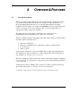
2 2 2.1 OVERVIEW & FEATURES General Description The Innova 3100 is a shaker that incorporates a triple eccentric counterbalanced drive to provide horizontal plane rotary motion in a ½ inch (12.7 mm) circular orbit. A Proportional/Integral (PI) microprocessor controller with instantaneous digital feedback controls the speed over a range of 25-400 RPM. It also provides temperature control over a range of 5°C above ambient to 80°C. For lower temperatures an optional water bath cooling coil is available.
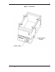
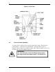
3 Figure 1: Front View Innova 3100 M1231-0050 Operating manual
4 Figure 2: Rear View 2.2 Universal Power Capability A voltage selector switch is used to select the appropriate voltage. This universal system adapts to worldwide power requirements. Voltage has been set prior to shipment. Innova shakers are available in 100V, 120V, 220V and 240V versions, and accommodate both 50 and 60 Hz frequencies. WARNING! It is critical that you check the voltage settings before you plug the unit into a power source. See Section 3.2.
5 2.3 Control Panel The control panel (see Figure 3 below) is located on the front of the instrument. It serves as the operator interface. The keypad has four keys marked START/STOP, ∆, ∇, and SELECT. A three-digit LED display provides numeric values as well as some letter codes. There are four function indicators and four status indicator lights on the control panel as well. A general description of the display, user interface keys and indicators follows.
6 Figure 3: Control Panel 2.3.2 User Interface Keys • START/STOP This key is used to start or stop the shaking motion. It will also activate or stop the timer when a timed run is desired. • SELECT This key is used to change the displayed parameter. • ∆, ∇ These keys are used to adjust the setpoint of a displayed parameter up or down. They also allow the user to enter the SET mode for setpoint changes. 2.3.
7 • SET Indicates that the shaker is in the SET mode, that setpoints are being displayed and that they can be altered. • TIME Indicates that the timer is in operation. Innova shakers can be programmed to run for a preset time from 0.1 hour to 99.9 hours. The timer can be disengaged to reset without stopping an ongoing run. • MUTE Indicates the status of the audible alarm. When the MUTE indicator is illuminated the audible alarm device is disabled. 2.3.
8 For operation below ambient temperature, the following kits are available for retrofit (by an NBS-authorized service technician only): • • 2.7 Cooling coil kit. Coolant Circulating System. Triple Eccentric Drive The Triple Eccentric Drive (see Figure 4 below) used in the Innova Shakers employs the same proven technology which has driven New Brunswick Scientific’s shakers for over 30 years. This drive mechanism utilizes a counterweight system to stabilize the rotary motion produced during operation.
9 2.8 Bearings Innova shakers employ shielded lubricated ball bearings of the highest quality. Shielded bearings minimize the generation of airborne particulates which may be disadvantageous in clean rooms or controlled environment areas. These bearings require no maintenance. 2.9 Motor The Innova 3100 Shaker uses a 3-phase brushless ball bearing DC motor. This low profile motor provides high torque along with quiet, efficient operation and low maintenance. This motor has a rating of 1/15 horsepower.
10 3 INSTALLATION & SET-UP The Innova 3100 is a versatile instrument that can be operated in a continuous fashion or set for a timed run. The following section describes set up and installation procedures. 3.1 Unpacking & Inspection Upon unpacking the unit, inspect it carefully for any apparent damage which may have occurred during transit. Report any damage to the carrier and to the New Brunswick Service Department (in the USA, call 1-800-631-5417) or to your New Brunswick Service Representative.
11 Voltage Configuration Table Innova 3100 Catalog # M1231-0001 M1231-0000 M1231-0002 M1231-0003 Voltage Electrical Service Package 100V 50/60Hz 120V 50/60Hz 220V 50/60Hz 240V 50/60Hz M1195-0350 M1195-0350 M1195-0360 M1195-0360 NOTE: Use of the Innova shakers requires a platform, which is a separate item. Available platforms are listed in Chapter 7. 3.3 3.3.1 Installation Space Requirements WARNING! There should be enough space around the mains/power connections to unplug the device.
12 Width Depth Height Inches Centimeters 19½ 27½ 17 43.2 69.9 36.8 The effective surface area required for operation is: Width Depth 3.3.2 Inches Centimeters 21½ 30 48.3 76.2 Hose Connections A ½ inch diameter reinforced hose is provided for water addition and drainage. Cut the hose into two lengths, to suit the distances from the water source to the machine. Install the hosing as follows, using Figure 6 on following page for reference: 1. 2. 3. 4.
13 Figure 6: Hose Connections The overflow tube is the farthest left of the three tubes that project down from the back of the bath. The other two tubes are used only when the cooling coil option is installed. NOTE: To minimize the development of rust inside the waterbath: • If you are using tap water in the bath, make sure the water has a low iron content. • If you are using distilled water, mix it with a small amount of tap water and/or add dissolved salts.
14 NOTE: If you are using tap water as coolant for the unit, it is preferable that the supply hose be attached to a supply valve, to minimize water use. 3.3.3 Platform Installation WARNING! Make sure shaker is unplugged from the mains/power before installing platform. A platform must be installed on the unit prior to use. To install the platform: 1. Make sure the circuit breaker on the right side of the unit is set to the OFF position. 2. Make sure the mains/power cord is unplugged. 3.
15 Figure 7: Platform Installation 3.3.4 Electrical Connections CAUTION! Be sure to use the following checklist BEFORE making electrical connections. 1. If you have not already done so, check the voltage selector switch at the rear of the unit to be sure that it is set to the appropriate voltage. 2. Remove the caution label from the rear of the unit. 3. Set the circuit breaker on the right side of the unit to the OFF position. 4.
16 4 4.1 OPERATION Starting the Innova 3100 To initially start the instrument, press the ON/OFF switch (located on the right side of the shaker) to the ON position. NOTE: The LED display will flash to indicate that the shaker has been off or the power to the shaker has been interrupted. To stop the flashing display, press any key. Press the SELECT key until the RPM indicator lights. If the shaker is running, the LED display will track the speed as it accelerates to the last entered speed setpoint.
17 4.3 Checking a Setpoint To check any setpoint: 1. Press SELECT until the desired indicator is lit. 2. Press either ∆ or ∇ to enter the SET mode, which will display the current setpoint. NOTE: Holding the ∆ or ∇ key down for more than 0.5 second will cause the speed, time or temperature setpoint to change. Should this occur, resetting will be necessary. 4.4 Timed Functions The shaker may be programmed to automatically stop after a preset time period of 0.1 hour to 99.9 hours.
18 4.4.2 Cancelling the Timer To cancel the timer WITHOUT stopping the shaker: 1. Press the SELECT key to light HRS. 2. Set the time by pressing the ∆ or ∇ key until the desired setpoint is displayed (0.1 - 99.9 hours). 3. While the SET LED is lit, press the START/STOP key. The TIME indicator will go out and the display will read “Off”. 4.5 Alarm Functions Innova shakers have an audible alarm which is activated at predetermined times. It may be deactivated in the following way: 1.
19 2. Increase or decrease the setpoint by pressing the ∆ or ∇ key. The temperature alarms, both audible and flashing light, are activated if the temperature is more than 1.0°C higher or lower than the temperature setpoint. The alarm will automatically deactivate as the unit achieves the set temperature. 4.6.2 Deactivating Temperature Control If desired, the temperature control system may be shut off during set-up for special investigations. To deactivate the temperature control system: 1.
20 from flasks, etc., the display temperature may differ from temperatures within the flasks themselves. If you wish to have the temperature display (“Indicated Temperature”) match the temperature at a given point, or match the average of a series of points within the chamber (“Actual Temperature”), proceed as follows: 1. Let the unit equilibrate at or near the desired temperature. Record the Indicated Temperature. 2. Record the Actual Temperature. 3.
21 The SET and MAINT indicators will flash and the accumulated running time will be displayed in hundreds of hours (i.e., “02” equals 200 hours; “102” equals 10,200 hours). This display will continue for 10 seconds and then default to the previous mode readout. 4.9 MAINT Indicator Light After 10,000 hours of operation, the MAINT indicator will light. Preventive maintenance is recommended at this point. The light can be deactivated by NBS service personnel.
22 3. Note the position of the water level and decide whether the desired level is higher or lower. 4. To raise the water level, note the position of the flexible tube graduations (these gradations and markings are for reference only). 5. Lift the tube up and push the excess tubing through the rear wall of the tank. As you raise the control, the solenoid will open and water will fill the bath until the new water level is established. 6.
23 5 MAINTENANCE & SERVICE The following section describes basic cleaning and maintenance instructions for the user. There are also troubleshooting and service procedures, and instructions to install optional features. These must be performed by a qualified service technician or engineer. WARNING! Before cleaning the instrument, and before a qualified Service Engineer performs any maintenance or service procedures, be sure to turn the power off (using the ON/OFF switch on the side).
24 WARNING! None of the following procedures should be attempted by anyone who is not a qualified Service Engineer or Technician. The ON/OFF switch must be turned off and the power cord disconnected prior to beginning any of these procedures. 5.3 Changing Fuses The unit is designed with a circuit breaker, which is used as an ON/OFF switch. There are two fuses on the rear of the unit. One is to protect the control circuitry and the other is to protect the motor circuit.
25 5.5 Replacing/Adjusting the Motor Drive Belt To replace or adjust the motor drive belt: 1. 2. 3. 4. Drain the water out of the bath. Turn off the power and remove the power cord. Lay the unit on its left side, using a soft pad to protect the finish. Remove the bottom cover using a Phillips (+) screwdriver. Retain the screws for reuse. 5. Rotate the large pulley (see Figure 9 below) and exert a light pressure to the belt so the belt feeds out of the pulley groove.
26 5.6 Replacing the Motor Assembly To replace the motor assembly: 1. 2. 3. 4. Drain the water out of the bath. Turn off the power and disconnect the power cord. Lay the unit on its left side, using a soft pad to protect the finish. Remove the bottom cover using a Phillips (+) screwdriver. Retain the screws for reuse. 5. Referring to Figure 10 below, remove the connector from the motor by lifting straight up. Figure 10: Motor Assembly Replacement 6.
27 11. Replace the pulley. Screw the set screw to the shaft flat, but do not tighten. 12. Position this assembly back onto the unit. Replace the two hex head bolts with their associated hardware, but do not tighten. 13. Replace the belt. Adjust the motor pulley height so that the belt is level as related to the drive pulley, then tighten the set screw. 14. Adjust the belt tension as shown in Figure 9, then tighten the two hex head bolts. 15.
28 Figure 11: Recorder Connector NOTE: The figure above is the pin-out diagram, as seen from the rear of the unit. The chart below identifies the pin application and scale. Pin # 6 2 7 3 5.9 Signal Name Speed Ground Temperature Ground Scale 1V = 100 rpm 1 V = 20° C Retrofitting the Cooling Coil Option The cooling coil option provides the ability to control temperatures below ambient in the Innova 3100. Control can be maintained at a temperature of 5°C or more above the coolant temperature.
29 To install the cooling coil kit: 1. Drain the water bath. 2. Turn the power OFF and disconnect the power cord. 3. Referring to Figure 12 below, remove the rear baffle by lifting straight up. The baffle will disengage from the retaining clips. Figure 12: Cooling Coil Installation 4. Remove the rear panel by removing the three screws on the lower edge of the panel, then slipping the panel down and away from the unit. 5.
30 14. Slide the four hose clamps to the ends of the hoses, allowing 1/8 inch to 3/16 inch of hose to extend beyond the clamps. Tighten the four clamps securely. 15. Cut the 16-foot hose into two pieces to suit the water supply and drain length requirement. 16. Attach the two long hoses to the cooling coil tubes with two clamps, allowing 1/8” to 3/16” of hose to extend beyond the clamps (see figure 2).
31 5.11 Replacing the Main Control Board 1. Switch the shaker OFF and disconnect the power cord. 2. Remove the five screws that hold the front panel (two screws on the sides and three on the bottom), and allow the front panel to lie on its face. 3. Remove the temperature control board: a. Disconnect the harness wiring from connectors J101, J102, J103 and J104 (see Figure 13 below). b. Remove the three 1/4” screws, the two nylon flat washers and the temperature sensor ground lug. c.
32 Figure 13: Control Board Replacement 4. Disconnect the harness wiring from connectors J1 and J2. 5. Remove the three hex spacers and 2 5/16 inch hex nuts. 6. Remove the green wire and keypad ground lead. 7. Remove the two screws that fasten the heat sink to the front panel bracket. 8. Lift the board out of the front panel and disconnect the keypad connector from J4. NOTE: Be careful not to lose the five ¼ inch spacers or the gray insulator. 9.
33 14. Reinstall the two 5/16 inch hex nuts and tighten. 15. Tighten the two heat sink mounting screws. 16. Reconnect the harness wiring to connectors J1 and J2. Make sure that each connector is properly positioned (keys mate and no pins remain exposed). 17. Reinstall the temperature control board: a. Snap the temperature control board onto the main control board, making sure the board-to-board connectors mate properly. b.
34 5.13 Service Parts List NBS Part Number P0380-3710 P0380-3532 P0420-1610 M1190-5300 P0320-0350 P0460-4091 P0360-4040 M1195-4001 M1190-9940 M1192-7000 M1190-5000 P0400-0980 P0400-4330 P0400-3011 P0400-2751 P0620-1370 M1195-3020 P0220-2382 M1195-8001 P0460-2090 P0720-2024 P0720-2021 M1190-6340 P0700-5302 M1231-6330 M1195-9420 M1231-0761 Description 0.16A 250V T Control Fuse 1.
35 6 SPECIFICATIONS This chapter provides technical details of interest, but not necessarily essential for operation of the instrument. SHAKING Speed Motion Indication Setpoint & Control Accuracy DRIVE 25-400 RPM ½ inch (12.7 mm) diameter circular orbit LED digital electric display, 1 RPM increments Digital adjustment with PI microprocessor control and instantaneous visual feedback ± 1 RPM Triple eccentric counterbalanced ball bearing drive.
36 AUTOMATIC RESTART • Unit will automatically restart after undesired power interruption. • Setpoints are maintained by non-volatile memory. • Interruption is indicated by a flashing display. MOTOR 1/15 HP, 3-phase brushless ball bearing DC motor. ELECTRICAL SERVICE • 100V, 120V, 220V, 240V • 50 or 60 Hz • 1100 VA Universal power entry system adapts to U.S. or International requirements. ELECTRICAL PROTECTION • Circuit breaker for main power. • Control circuits provided with separate fuse.
37 Innova 3100 M1231-0050 Operating manual
38 7 ACCESSORIES This chapter outlines the wide variety of accessories available for use with the Innova 3100. 7.1 Interchangeable Platforms Following are 12 inch x 16½ inch (30.5 cm x 42.4 cm) stainless steel platforms: Catalog No.
39 7.3 Test Tube Racks for Subplatform The following racks must be mounted on the subplatform (M1231-9939): 7.
40 Catalog Number ACE-6000S ACE-2800S ACSB-500S ACSB-1000S 7.6 Type of Clamp 6.0L Erlenmeyer Clamp 2800mL Fernbach Flask Clamp 500mL Media Bottle Clamp 1.0L Media Bottle Clamp Clamp Mounting Hardware NBS flask clamps are used on a variety of shaker platforms. Flat head screws of different lengths and thread pitch are used to secure the clamp. The tables below identify the proper screw for your shaker application by reference to the head style: 7.6.
41 8 8.
42 9 # °C Indicator, 7 Flashing of, 20 Cooling Coil Option, 7, 13 Retrofitting the, 28 Counterbalanced Drive Mechanism, 8 Counterweight, 8 Current Temperature, 7 D * * Indicator, 7 A Accessories, 7, 38, 39 Accessory Flask Clamps, 39 Actual Temperature, 19 Adjusting the Motor Drive Belt, 25 Alarm Conditions, 2 Alarm Functions, 18 Alarms, 2, 18, 35 Ambient Operating Environment, 35 Audible Alarm, 2 Automatic Restart Features, 36 B Bearings, 8 Belt Adjusting the, 25 Replacing the, 25 INDEX Damage Repor
43 G Gable Cover, 7, 18, 39 H Half Platforms, 7, 38 Heater Description, 35 Hose Connections, 4, 12 Hours Remaining Display of, 5 How to Adjust the Motor Drive Belt, 25 How to Cancel the Timer, 18 How to Drain the Bath, 22 How to Replace the Motor Assembly, 26 How to Replace the Motor Drive Belt, 25 How to Set the Temperature, 18 How to Set the Timer, 17 HRS Indicator, 7 I Indicated Temperature, 19 Inspecting the Instrument, 10 Installation Instructions, 11 Installing a Platform, 14 Installing the Hoses,
44 Total Running Time, 20 Supporting Arms, 8, 14, 21 T Table of Contents, iv Temperature Display of, 5 Temperature Accuracy, 35 Temperature Control, 2, 18 Deactivating the, 19 Reactivating the, 19 Temperature Control Board, 9 Replacing the, 33 Temperature Control Stability, 35 Temperature Correction Value, 19 Temperature Offset Calibration, 19 Temperature Range, 2, 18, 35 Temperature Safety Feature, 35 Temperature Setpoint, 35 Setting the, 18 Temperature Uniformity, 35 Test Tube Racks, 39 TIME Indicator,