
User`s manual


- 11 -
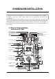
3 HARDWARE INSTALLATION
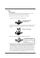
Before removing or installing any of these devices including CPU, DIMMs,
Add-On Cards and Cables, please make sure to unplug the onboard power
connector.
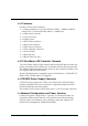
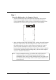
This section outlines how to install and configure your mainboard. Refer to the following
mainboard layout to help you to identify various jumpers, connectors, slots, and ports.
Then follow these steps designed to guide you through a quick and correct installation of
your system.
3.1 Step-by-Step Installation
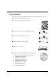
Accessories Of FB61
C
A
R
6
1
D
-
5
6
0
0
3
0
2
9
8
5
2
6
0
7
C
F
I
C
S
PhoneixBios
D6868 BIOS
PHOENIX 1998
165186837
JP1
JP6
JP11
PCI1
JP2
FAN1
1
1
1
1
1
1
1
JP8
IDE2
FDD1
IDE1
ATX1
ATX2
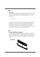
DIMM1
FAN2
JP7
IR
DIMM2
JP13
1
-
c AmMega 87-96
MGR235
C
F
3
3
7
0
2
5
1
S
L
7
3
2
I
N
T
E
L
0
2
I
n
t
e
l
F
W
8
2
8
0
1
E
B
P
H
I
L
I
P
P
I
N
E
S
SPDIF
JP3
1
FAN3
1
VT 6307
0346CD TAIWAN
2HA1007637
C M
TM
JP14
R
T
L
8
1
0
0
C
3
A
2
4
8
Q
1
3
4
5
T
A
I
W
A
N
KB1
LAN2
USB2
AUDIO
USB1
3A175Q1 342F
ALC650
USB4
1
USB5
JP16
1
1
1
AGP
J1
1
1
PS/2 Keyboard/Mouse Connectors
COM1 & VGA Connectors
LAN & USB1.1/2.0 Connectors
LAN & USB1.1/2.0 Connectors
IR Header-
JP7
One PCI Slot
One AGP Slot
Front Panel Connector -
JP16
Clear CMOS-
JP1
Front Panel Connector
-
JP13
Two DIMM Slots
Two IDE Connectors -
IDE1/IDE2
One Floppy Connector
ATX Power Connector-
ATX1
FAN2
SOCKET 478
FAN3
Center/Bass/Rear-Out/Front-OutHeader
SPDIF IN/OUT Connector-
JP3
ATX +12V Power Connector -
ATX2
Intel 82801EB Chipset
Intel 82865G Chipset
Serial ATA Connectors
-
SATA1/SATA2
EXT. Print Port-
JP8
CD-IN Connector-
JP11
FAN1
Wireless KB/MS Connector -
JP6
I
T
E
8
7
1
2
F
USB Header-
USB4
USB Header-
USB5
One PCI Slot