
Specifications

Installation EP-68LXR
Page 3-8
Section 3-4
Device Connectors
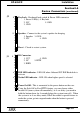
Please install the motherboard into the chassis.
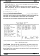
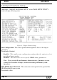
Now that your motherboard is installed you are ready to connect all your connections
(figure 12).
J2: Chassis Panel Connector
• Keylock, Speaker, Reset
J3: Turbo LED, HDD LED, IR Conn., Sleep/Power_ON
J4: CPU Fan Power
• A plug-in for the CPU Fan Power
J5: Power Supply Fan Monitoring
• A plug-in for the Power supply so that BIOS can monitor the RPM’s
J6: Chassis Fan Power
• A plug-in for the chassis Fan Power
J7: WOL Connector
J8: SB-Link Header
PS1: PS2 Mouse Header
USB1: USB Header
IDE1: Primary IDE
IDE2: Secondary IDE
FDD1: Floppy Controller Connector
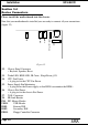
Figure 12
USB
COM2
COM1
PS/2 Mouse Conn
LPT
KB Conn.