
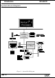
Specifications

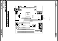

Installation EP-68LXR
Page 3-4
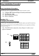
DIMM Module Installation
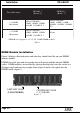
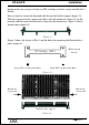
Figure 5 displays the notch marks and what they should look like on your DIMM
memory module.
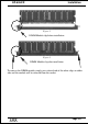
DIMMs have 168-pins and two notches that will match with the onboard DIMM
socket. DIMM modules are installed by placing the chip firmly into the socket at a
90 degree angle and pressing straight down (figure 6) until it fits tightly into the
DIMM socket (figure 7).
Figure 5
* SDRAM only supports 8, 16, 32, 64, 128MB DIMM modules.
Table 1
yromeMlatoT
1MMID
)0knaB(
2MMID
)1knaB(
BM652=
mumixaM
*MARDS/ODE
,BM23,BM61,BM8
1XBM821,BM46
*MARDS/ODE
,BM23,BM61,BM8
BM652,BM821,BM46
1X
BM821=
mumixaM
*MARDS/ODE
,BM23,BM61,BM8
1XBM821,BM46
enoN
CENTER KEY ZONE
(3.3 V DRAM)
LEFT KEY ZONE
(UNBUFFERED)