EP-68LXR APentium®IIProcessorbasedAGPmainboard TRADEMARK All products and company names are trademarks or registered trademarks of their respective holders. These specifications are subject to change without notice. Manual Revision 2.
EP-68LXR Technical Support Services If you need additional information, help during installation or normal use of this product, please contact your retailer. If your retailer can not help, you may E-Mail us with any questions at the following address tech@epox.com Record your serial number before installing your EP-68LXR mainboard.
EP-68LXR User Notice No part of this product, including the product and software may be reproduced, transmitted, transcribed, stored in a retrieval system, or translated into any language in any form by any means without the express written permission of EPoX Computer Company (here in after referred to as EPoX) except documentation kept by the purchaser for backup purposes.
EP-68LXR Table of Contents Section 1 Introduction Components Checklist .................................... 1-1 Overview Pentium II ....................................................... 1-2 S.E.C. Cartridge Terminology ......................... 1-3 Accelerated Graphics Port .............................. 1-4 Hardware Monitoring ..................................... 1-4 Desktop Management Interface ...................... 1-4 Power-On/Off (Remote) .................................
EP-68LXR Integrated Peripherals ..................................... 4-19 Change Supervisor or User Password ............. 4-24 IDE HDD Auto Detection ............................... 4-24 HDD Low Level Format ................................. 4-27 Save & Exit Setup .......................................... 4-27 Exit Without Saving ......................................... 4-27 Section 5 DMI DMI Access ................................................... 5-1 Section 7 Appendix Appendix A Memory Map ...
EP-68LXR Introduction Section 1 INTRODUCTION Components Checklist ü ü ü ü ü ü A. (1) EP-68LXR mainboard B. (1) EP-68LXR user’s manual C. (1) Floppy ribbon cable D. (1) Hard drive ribbon cable E. (1) Heatsink Support Unit (optional) F. (1) PS/2 Mouse Connector G. (1) Bus master drivers H.
Introduction EP-68LXR Overview Pentium II The Pentium® II Processor is the follow-on to the Pentium® Processor. The Pentium® II Processor, like the Pentium® Pro processor, implements a Dynamic Execution micro-architecture -- a unique combination of multiple branch prediction, data flow analysis, and speculative execution. This enables the Pentium® II Processor to deliver higher performance than the Pentium® processor, while maintaining binary compatibility with all previous Intel architecture processors.
EP-68LXR Introduction processor. This is the model used in past packaging technologies like PGA, TCP, PQFP, DIP, etc. S.E.C. Cartridge Terminology • Pentium® II Processor The new enclosed card packaging technology is called a “Single Edge Contact cartridge.” This is similar to previous names for packaging technology such as PGA or TCP.
Introduction EP-68LXR Accelerated Graphics Port (AGP or A.G.P.) Typically, 3D graphics rendering requires a tremendous amount of memory, and demands ever increasing throughput speed as well. As 3D products for the personal computer become more and more popular, these demands will only increase. This will cause a rise in costs for both end users and manufacturers. Lowering these costs as well as improving performance is the primary motivation behind AGP.
EP-68LXR Introduction Power-On/Off (Remote) The EP-68LXR has a single 20-pin connector for ATX power supplies. For ATX power supplies that support the Remote On/Off feature, this should be connected to the systems front panel for system Power On/Off button. The systems power On/ Off button should be a momentary button that is normally open. The EP-68LXR has been designed with “Soft Off" functions.
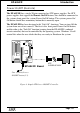
Introduction EP-68LXR System Block Diagram PAC PCI Bridge and memory controller 443LX/443EX PIIX4/PIIX4E I/O Bridge Figure 5: System Block Diagram Page 1-6
EP-68LXR Features Section 2 FEATURES EP-68LXR Features: • EP-68LXR is based on the Pentium® II Processor operating at 233 ~ 333 MHz on Slot 1. The board is configured by an DIP Switch to match your CPU clock speed. • Designed with Intel’s 82443 LX (or 82443 EX) AGPset. • Supports up to 256MB of DRAM (minimum of 8 MB) on board (please see Section 3-2). • EP-68LXR will support Error Checking and Correcting (ECC) when using parity DRAM memory modules.
Features EP-68LXR • Supports the Universal Serial Bus (USB) Header. The onboard PIIX4/PIIX4E chip provides the means for connecting PC peripherals such as; keyboards, joysticks, telephones, and modems. • Built-in ATX 20-pin and AT 12-Pin power supply connector. • Software power-down when using Windows® 95. • Supports ring-in feature (remote power-on through external modem, allows system to be turned on remotely. • Resume by Alarm - Allows your system to turn on at a preselected time.
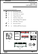
Page 3-1 J5 PS/2 Secondary IDE SB-Link J8 J7 Figure 1 POWER_ON IDE1 IDE2 Flash Memory for BIOS J6 ISA Slot #2 5 Chassis FAN ISA Slot #1 1 HD/LED TB/LED Bank 1 WOL PCI Slot #1 IR CONN.
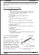
Installation EP-68LXR Easy Installation Procedure Easy Installation Procedure The following must be completed before powering on your new system: 3-1. 3-2. 3-3. 3-4. Configure DIP Switch and Jumper to match your hardware Install memory chips Install Pentium II Processor Device Connectors Section 3-1 Configure DIP Switch EPoX designs all motherboards with a DIP Switch to make your install fast and easy.
EP-68LXR Installation Section 3-2 System Memory Configuration Memory Layout The EP-68LXR supports (2) 168-pin DIMMs (Dual In-line Memory Module). The DIMMs can be either EDO (Enhanced Data Out) or SDRAM (Synchronized DRAM). • DIMM SDRAM may be 83MHz (12ns), 100MHz (10ns) or 120MHz (8ns) bus speed. • If you use both 50ns and 60ns memory you must configure your BIOS to read 60ns. • When using Synchronous DRAM we recommend using the 4 clock variety over the 2 clock.
Installation Tot a l M e mor y EP-68LXR DI M M 1 (Ba nk 0) DI M M 2 (Ba nk 1) = 256MB Maximum EDO /SDRAM* 8MB, 16MB, 32MB, 64MB, 128MB X 1 EDO /SDRAM* 8MB, 16MB, 32MB, 64MB, 128MB, 256MB X1 = 128MB Maximum EDO /SDRAM* 8MB, 16MB, 32MB, 64MB, 128MB X 1 N one * SDRAM only supports 8, 16, 32, 64, 128MB DIMM modules. Table 1 DIMM Module Installation Figure 5 displays the notch marks and what they should look like on your DIMM memory module.
EP-68LXR Installation Figure 5 DIMM Module clip before installation Figure 6 DIMM Module clip after installation To remove the DIMM module simply press down both of the white clips on either side and the module will be released from the socket.
Installation EP-68LXR Section 3-3 Installing a Pentium II Processor The EP-68LXR uses the Single Edge Contact (SEC) slot for a Pentium II processor packaged in an SEC cartridge. The SEC slot is not compatible with other nonPentium II processors. Please have ready the following list of components so that we may install the processor onto the motherboard. 1. 2. 3.
EP-68LXR Installation bottom make sure you press firmly on SEC cartridge to firmly secure into the Slot 1 Socket. Now we need to secure the heatsink with the top half of the support (figure 11). Take the top piece of the support and slide it into the bottom fin (figure 11) on the heatsink and then push forward until it clips into the bottom base (figure 9) that is already there (figure 11). Figure 9 Figure 9 shows the layout of Slot 1 and the holes for mounting the Heatsink base piece (figure 8).
Installation EP-68LXR Section 3-4 Device Connectors Please install the motherboard into the chassis. Now that your motherboard is installed you are ready to connect all your connections (figure 12). LPT P S /2 M o u se C o n n COM 2 USB COM 1 K B C o n n. Figure 12 J2: Chassis Panel Connector • Keylock, Speaker, Reset J3: Turbo LED, HDD LED, IR Conn.
EP-68LXR Installation Section3-4 Device Connectors (continued) J2 1 KeyLock - Keyboard lock switch & Power LED connector 1. Power LED(+) 4. Keylock 2. N/C 5. GND 3. GND 1 Speaker - Connect to the system's speaker for beeping 1. Speaker 3. GND 2. N/C 4. GND Reset - Closed to restart system. J3 1 + + IR Connector 1. VCC 2. NC 3. IRRX 4. GND 5.
EP-68LXR BIOS Section 4 AWARD BIOS SETUP BIOS Instructions Award’s ROM BIOS provides a built-in Setup program which allows user to modify the basic system configuration and hardware parameters. The modified data will be stored in a battery-backed CMOS, so that data will be retained even when the power is turned off. In general, the information saved in the CMOS RAM will stay unchanged unless there is a configuration change in the system, such as hard drive replacement or a device is added.
BIOS EP-68LXR The menu displays all the major selection items. Select the item you need to reconfigure. The selection is made by moving the cursor (press any direction key ) to the item and pressing the ‘Enter’ key. An on-line help message is displayed at the bottom of the screen as the cursor is moved to various items which provides a better understanding of each function. When a selection is made, the menu of the selected item will appear so that the user can modify associated configuration parameters.
EP-68LXR BIOS NOTE: The “Halt On:” field is used to determine when to halt the system by the BIOS if an error occurs. NOTE: Floppy 3 Mode support is a mode used to support a special 3.5” drive used in Japan. This is a 3.5” disk that stores only 1.2 MB, the default setting for this is disabled. 4-2 BIOS Features Setup Selecting the “BIOS FEATURES SETUP” option in the CMOS SETUP UTILITY menu allows users to change system related parameters in the displayed menu.
BIOS EP-68LXR Enabled: Activates automatically when the system boots up causing a warning message to appear when anything attempts to access the boot sector. Disabled: No warning message will appear when anything attempts to access the boot sector. Note: Many disk diagnostic programs that access the boot sector table can trigger the virus warning message. If you plan to run such a program, we recommend that you first disable the virus warning.
EP-68LXR BIOS Swap Floppy Drive: This will swap your physical drive letters A & B if you are using two floppy disks. The default is Disabled. Enabled: Floppy A & B will be swapped under the O/S. Disabled: Floppy A & B will be not swapped. Boot Up Floppy Seek: During Power-On-Self-Test (POST), BIOS will determine if the floppy disk drive installed is 40 or 80 tracks. Only 360K type is 40 tracks while 760K, 1.2MB and 1.44MB are all 80 tracks. The default is Enabled.
BIOS EP-68LXR Typematic Rate Setting: This determines the keystrokes repeat rate. The default is Disabled. Enabled: Allows typematic rate and typematic delay programming. Disabled: The typematic rate and typematic delay will be controlled by the keyboard controller in your system. Typematic Rate (Chars/Sec): This is the number of characters that will be repeated by a keyboard press. The default is 6. 6: 6 characters per second. 10: 10 characters per second. 15: 15 characters per second.
EP-68LXR BIOS OS Select For DRAM > 64MB: Some operating systems require special handling. Use this option only if your system has greater than 64MB of memory. The default is Non-OS2. OS2: Select this if you are running the OS/2 operating system with greater than 64MB of RAM. Non-OS2: Select this for all other operating systems and configurations. Video BIOS Shadow: This option allows video BIOS to be copied into RAM. Video Shadowing will increase the video performance of your system.
BIOS EP-68LXR 4-3 Chipset Features Setup Choose the “CHIPSET FEATURES SETUP” in the CMOS SETUP UTILITY menu to display following menu. Figure 4: Chipset Features Setup Auto Configuration: This selects predetermined optimal values of the chipset parameters. The default is Enabled. Enabled: This enables auto-configuration and provides the option to select predefined timing modes. Disabled: This allows the user to specify DRAM timing parameters.
EP-68LXR BIOS 50ns: (Faster) Burst Wait State, for 50ns EDO DRAM. 60ns: (Slower) Burst Wait State, for 60ns Fast Page Mode/EDO DRAM. MA Additional Wait State: This allows the option to insert an additional wait state before the beginning of a memory read. Use of this option may be required to achieve compatibility with some system configurations. The default is Slow. Fast: Inserts no wait state. Slow: Inserts one wait state for the memory cycle.
BIOS EP-68LXR x222: Use of this option may cause conflicts with some system configurations. x333: This is used for standard system configurations. DRAM Data Integrity Mode: Use this option to configure the type of DRAM in your system. The default is Non-ECC. Non-ECC: If your memory is Non-ECC memory, choose this option. ECC: If your memory is ECC memory, choose this option. CPU-To-PCI IDE Posting: This option allows the computer to post write cycles from the CPU to the PCI IDE interface.
EP-68LXR BIOS 8 Bit I/O Recovery Time: This function allows you to set the wait state that is added to an 8 bit ISA instruction originated by the PCI bus. The default is 3. NA: 1: 1 3: 3 5: 5 7: 7 No wait state wait states wait states wait states wait states 8: 2: 4: 6: 8 2 4 6 wait wait wait wait states states states states 16 Bit I/O Recovery Time: This function allows you to set the wait state that is added to an 16 bit ISA instruction originated by the PCI bus. The default is 2.
BIOS EP-68LXR AGP Aperture Size: The amount of system memory that the AGP card is allowed to share. The default is 4. 4: 4MB of systems memory accessable by the AGP card. 8: 8MB of systems memory accessable by the AGP card. 16: 16MB of systems memory accessable by the AGP card. 32: 32MB of systems memory accessable by the AGP card. 64: 64MB of systems memory accessable by the AGP card. 128: 128MB of systems memory accessable by the AGP card. 256: 256MB of systems memory accessable by the AGP card.
EP-68LXR BIOS Current CPU Temperature: This is the current temperature of the CPU. Current Power FAN Speed: The current power fan speed in RPMs. Current CPU FAN Speed: The current CPU fan speed in RPMs. Current Chassis FAN Speed: The current chassis fan speed in RPMs. CPU(V): The voltage level of the CPU. Note: The hardware information above is not available for a mainboard without NS LM75/LM78 ICs.
BIOS EP-68LXR Power Management: Use this to select your Power Management selection. The default is User define. Disabled: The system operates in NORMAL conditions (Non-GREEN), and the Power Management function is disabled. Max. saving: Maximum power savings. Inactivity period is 1 minute in each mode. Min. saving: Minimum power savings. Inactivity period is 1 hour in each mode. User define: Allows user to define PM Timers parameters to control power saving mode.
EP-68LXR BIOS MODEM Use IRQ: Name the interrupt request (IRQ) line assigned to the modem (if any) on your system. Activity of the selected IRQ always awakens the system. Default is IRQ 3. N/A: No IRQ is used. 3: 4: IRQ 4 5: 7: IRQ 7 9: 10: IRQ 10 11: IRQ IRQ 3 IRQ 5 IRQ 9 11 The EP-68LXR supports HDD Power Down, Doze and Standby power saving functions when using the Intel Pentium II Processor. The default is Disabled Doze Mode: The “Doze” mode timer starts to count when no “PM events” have occurred.
BIOS EP-68LXR Resume by Ring: This option is used to set the remote ring in feature. This option is only available when Power Loss Recovery is Enabled. The default is Enabled. Enabled: The system can use remote ring-in to wake the system up. Disabled: The system cannot use remote ring in to wake system up. Power Loss Recovery: If the power to the system is cut off the system will turn itself back on with no user intervention. The default is Enabled.
EP-68LXR BIOS 4-5 PNP/PCI Configuration The PNP/PCI configuration program is for the user to modify the PCI/ISA IRQ signals when various PCI/ISA cards are inserted in the PCI or ISA slots. WARNING: Conflicting IRQ’s may cause the system to not find certain devices. Figure 6: PCI Configuration Setup PNP OS Installed: Do you have a PNP OS installed on your system. The default is No. Yes: Select if you are using a PNP OS No: Select if your OS does not support PNP.
BIOS EP-68LXR Reset Configuration Data: This setting allows you to clear ESCD data. The default is Disabled Disabled: Normal Setting. Enabled: If you have plugged in some Legacy cards to the system and they were recorded into ESCD (Extended System Configuration Data), you can set this field to Enabled in order to clear ESCD. PCI IDE IRQ Map To: This item allows the user to configure the system for the type of IDE hard disk controller in use.
EP-68LXR BIOS 4-6 Load Setup Defaults The “LOAD SETUP DEFAULTS” function loads the system default data directly from ROM and initializes the associated hardware properly. This function will be necessary only when the system CMOS data is corrupted.
BIOS EP-68LXR IDE HDD Block Mode: IDE Block Mode allows the controller to access blocks of sectors rather than a single sector at a time. The default is Enabled. Enabled: Enabled IDE HDD Block Mode. Provides higher HDD transfer rates. Disabled: Disable IDE HDD Block Mode. Onboard Primary PCI IDE: The default value is Enabled. Enabled: Enables Onboard IDE primary port. Disabled: Disables Onboard IDE primary port. Onboard Secondary PCI IDE: The default is Enabled.
EP-68LXR BIOS Mode 0~4: Manually set the IDE Programmed interrupt mode. IDE Primary Master UDMA: This allows you to select the mode of operation for the hard drive. The default is Auto. Auto: The computer will select the optimal setting. Disabled: The hard drive will run in normal mode. IDE Primary Slave UDMA: This allows you to select the mode of operation for the hard drive. The default is Auto. Auto: The computer will select the optimal setting. Disabled: The hard drive will run in normal mode.
BIOS EP-68LXR OnBoard Primary PCI IDE: This option turns on and off the onboard primary IDE. The default is enabled. Enabled: This activates the primary PCI IDE. Disabled: This disables the primary PCI IDE and frees up the resource. OnBoard Secondary PCI IDE: This option turns on/off the onboard secondary IDE. The default is enabled. Enabled: This activates the secondary PCI IDE. Disabled: This disables the secondary PCI IDE and frees up its resources. KBC input clock: This sets the keyboard clock value.
EP-68LXR BIOS Onboard IR Controller: IrDA Controller. The default is Enabled. IR Address Select: The port location of the IR controller. The default is 2E8H. IR Mode: The mode of the IR controller. The default is IrDA IR Transaction Delay: The default is Enabled. IR IRQ Select: The default is IRQ 10 IR Mode use DMA: The default is Disable. Onboard Parallel port: This field allows the user to configure the LPT port. The default is 378H / IRQ7. 378H: Enable Onboard LPT port and address is 378H and IRQ7.
BIOS EP-68LXR 4-8 Change Supervisor or User Password To change the password, choose the “SUPERVISOR PASSWORD or USER PASSWORD” option from the CMOS SETUP UTILITY menu and press [Enter]. NOTE: Either “Setup” or “System” must be selected in the “Security Option” of the BIOS FEATURES SETUP menu. 1. If CMOS is corrupted or the option was not used, a default password stored in the ROM will be used.
EP-68LXR BIOS Figure 8: IDE HDD Auto Detection NOTE: HDD Modes The Award BIOS supports 3 HDD modes : NORMAL, LBA & LARGE NORMAL mode Generic access mode in which neither the BIOS nor the IDE controller will make any transformations during accessing. The maximum number of cylinders, head & sectors for NORMAL mode are. 1024, 16 & 63 no. Cylinder x no. Head x no. Sector x no.
BIOS EP-68LXR LBA (Logical Block Addressing) mode: A new HDD accessing method to overcome the 528 Megabyte bottleneck. The number of cylinders, heads & sectors shown in setup may not be the number physically contained in the HDD. During HDD accessing, the IDE controller will transform the logical address described by sector, head & cylinder into its own physical address inside the HDD. The maximum HDD size supported by LBA mode is 8.4 GigaBytes which is obtained by the following formula: no.
EP-68LXR BIOS UNIX operating systems do not support either LBA or LARGE and must utilize the Standard mode. UNIX can support drives larger than 528MB. 4-10 HDD Low Level Format Interleave: Select the interleave number of the hard disk drive you wish to perform a low level format on. You may select from 1 to 8. Check the documentation that came with the drive for the correct interleave number, or select 0 for automatic detection.
EP-68LXR DMI Access Section 5 DMI ACCESS DMI Access DMI, or desktop Management Interface, is a feature that is able to auto-detect and record information about your computer system. This information is used by computing professionals to accurately determine your system configuration and to diagnose and resolve problems. The computer’s BIOS will detect and record as much information as it is able to, and will store that information in a special location in the BIOS.
EP-68LXR Appendix Appendix A: A-1 MEMORY MAP Address Range [00000-7FFFF] [80000-9FBFF] [9FC00-9FFFF] [A0000-C7FFF] [C8000-DFFFF] [E0000-EEFFF] [EF000-EFFFF] Size 512K 127K 1K 160K 96K 60K 4K [F0000-F7FFF] [F8000-FCFFF] [FD000-FDFFF] [FE000-FFFFF] 32K 20K 4K 8K Description Conventional memory Extended Conventional memory Extended BIOS data area if PS/2 mouse is installed Available for Hi DOS memory Available for Hi DOS memory and adapter ROMs Available for UMB Video service routine for Monochrome & CGA
Appendix [3D0-3DF] [3F0-3F7] [3F8-3FF] EP-68LXR CGA adapter. FLOPPY DISK controller. SERIAL port 1. A-3 TIMER & DMA CHANNELS MAP TIMER MAP: TIMER Channel 0 TIMER Channel 1 TIMER Channel 2 DMA CHANNELS: DMA Channel 0 DMA Channel 1 DMA Channel 2 DMA Channel 3 DMA Channel 4 DMA Channel 5 DMA Channel 6 DMA Channel 7 System timer interrupt. DRAM REFRESH request. SPEAKER tone generator. Available. Onboard ECP (Option). FLOPPY DISK (SMC CHIP). Onboard ECP (default). Cascade for DMA controller 1. Available.
EP-68LXR 14 15 Appendix Onboard HARD DISK (IDE1) channel. Onboard HARD DISK (IDE1) channel. A-5 RTC & CMOS RAM MAP RTC & CMOS: 00 Seconds. 01 Second alarm. 02 Minutes. 03 Minutes alarm. 04 Hours. 05 Hours alarm. 06 Day of week. 07 Day of month. 08 Month. 09 Year. 0A Status register A. 0B Status register B. 0C Status register C. 0D Status register D. 0E Diagnostic status byte. 0F Shutdown byte. 10 FLOPPY DISK drive type byte. 11 Reserve. 12 HARD DISK type byte. 13 Reserve. 14 Equipment type.
Appendix EP-68LXR Appendix B: B-1 POST CODES ISA POST codes are typically output to I/O port address 80h. POST (hex) DESCRIPTION 01-02 Reserved. C0 Turn off OEM specific cache, shadow. 03 1. Initialize EISA registers (EISA BIOS only). 2. Initialize all the standard devices with default values Standard devices includes. - DMA controller (8237). - Programmable Interrupt Controller (8259). - Programmable Interval Timer (8254). - RTC chip. 04 Reserved 05 1. Keyboard Controller Self-Test. 06 2.
EP-68LXR Appendix 0C 0D Initialization of the BIOS Data Area. (40:ON - 40:FF) 1. Program some of the Chipset's value according to Setup. (Early Setup Value Program) 2. Measure CPU speed for display & decide the system clock speed. 3. Video initialization including Monochrome, CGA, EGA/VGA. If no display device found, the speaker will beep. 0E 1. Test video RAM. (If Monochrome display device found) 2. Show messages including. - Award Logo, Copyright string, BIOS Data code & Part No.
Appendix 3E 3F-40 BF 41 42 43 45 44 45 46-4D 4E 4F 50 51 52 53 60 A-6 EP-68LXR Try to turn on Level 2 cache. Note: Some chipset may need to turn on the L2 cache in this stage. But usually, the cache is turn on later in POST 61h. Reserved. 1. Program the rest of the Chipset's value according to Setup. (Later Setup Value Program) 2. If auto-configuration is enabled, program the chipset with pre-defined Values. Initialize floppy disk drive controller. Initialize Hard drive controller.
EP-68LXR 61 62 63 FF Appendix 1. Try to turn on Level 2 cache. Note: If L2 cache is already turned on in POST 3D, this part will be skipped. 2. Set the boot up speed according to Setup setting. 3. Last chance for Chipset initialization. 4. Last chance for Power Management initialization. (Green BIOS only) 5. Show the system configuration table. 1. Setup daylight saving according to Setup value. 2. Program the NUM Lock, typematic rate & typematic speed according to Setup setting. 1.
Appendix EP-68LXR Appendix C NOTE: The "LOAD SETUP DEFAULTS" function loads the system default data directly from ROM and initializes the associated hardware properly. This function will be necessary when you accept this mainboard, or the system CMOS data is corrupted.