Plasma Technics Inc. 1900 William St. Racine, WI 53404-1875 Phone : (262) 637-7180 fax : (262) 637-7157 Web Page http://www.plasmatechnics.com E-Mail: sales@plasmatechnics.
Plasma Technics Inc. 1900 William St. Racine, WI 53404-1875 Phone : (262) 637-7180 fax : (262) 637-7157 Web Page http://www.plasmatechnics.com E-Mail: sales@plasmatechnics.
Table of Contents SSD110 Solid State Drive ………………………..… page 4 DAT210 Digital Auto Tune Inverter………… page 6 DAT210 Inverter Assembly ………………………… page 9 SSD210 12DC/AC Inverter ……………….…..…… page 12 SSD310 Solid State Drive …………….….…..…… page 14 Unico 1105 Inverter …………………………….….… page 16 Electronic Ozone Transformer ET and ETI series 50 & 100 watt ….…… page 20 Solid State Ozone Power Supply 10 watt… page 23 Severe-Application Ozone Transformers Oil 70 – 250 watt ………………………...
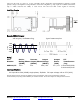
1.8kva – 3.6kva / high frequency SSD110 - Solid State Drive The SSD110 is a new, second-generation, Pulse Density Modulation (PDM) enhanced, single-phase inverter providing linear plasma control with a turn-down to 10%. Higher power capacity, enhanced controls, improved internal fault protection and identical mounting are the product’s cornerstones.
lock-out in the event of power loss. A user- selectable output compensation circuit maintains a relatively constant primary voltage as the input line-voltage fluctuates. Customer configurable op. amp. inputs are available at the barrier strip to enable customers the ability to scale, invert, mix and level shift control signals if necessary. Installation Drawing Example SSD110 Outputs: Full Frequency / Full RMS Voltage Typical PDM Waveform 0.50 0.00 0 0 Voltage 1.00 -0.50 -1.
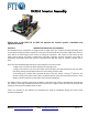
250w - 4kw / 50hz - 30khz DAT210 – Digital Auto-Tune Inverter The DAT210 is a new Microcontroller design that automatically determines the optimum system operating frequency (resonance). Years in the making, this technology will, for the first time, make high-efficiency self optimizing systems available to everyone. This single-phase inverter provides a linear means to adjust corona by using Pulse Density Modulation (PDM), with frequencies up to 30khz.
Features Continued: User-adjustable HIGH and LOW load-current bracketing. Either high current or low current produce a fault which is reported to the terminal strip as well as LEDs, which can then be handled as a soft fault or hard fault. Soft means a user-provided PLC can decide what action is taken before the inverter is disengauged. A hard fault will automatically provide an OFF command to disengage the inverter output.
Example DAT210 Outputs: Full Frequency / Full RMS Voltage Typical PDM Waveform 0.50 0.00 0 0 Voltage 1.00 -0.50 -1.00 Sizing: Part Number DAT210 Device Rating/Phase (ARMS) 25.0 Inverter Output/Phase (ARMS) 15.0 Output Voltage (VRMS) 240 / 120 Output Power (KVA) PTI Transformers /Leg 3.6 / 1.8 Input specifications: AC input 90 to 264 (VRMS) single-phase, 50/60hz. DC input voltage 120 to 373 (VDC). Plasma Technics Inc. 1900 William St.
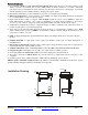
DAT210 Inverter Assembly Please refer to the DAT 210 or SSD 110 manuals for inverter specific installation and operational details. SECTION 1. REASONS FOR SPECIFYING THE ASSEMBLY The DAT210 inverter component is designed with a single phase line rectifier providing pulsating direct current (DC) to large input filter capacitors. If the line is connected directly to the line input of the inverter, there will be an initial large inrush current to charge the capacitors.
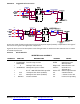
SECTION 2. Suggested soft start circuits FUSE MOV FUSE 3 4 5 50 OHMS 25 W FUSE RELAY SPST FUSE MOV MOV FUSE 3 4 5 MOV Circuits are shown for both single phase (top) and three phase inputs (bottom). Components to the right of the inverter are typical ozone generator components. A general rule is to use the three phase circuit if the generator is rated over 2 KW. However this is a matter of individual preference. Section 3 Bill of Materials INVERTER 70250 ASSEMBLY QUANTITY 1 1 1 1 1 1 1 PART NO.
Section 4 Dimensions D.C. LINK CHOKE PDM CONTROL POTENTIOMETER FULL CLOCKWISE EQUALS MAXIMUM SOFT START RELAY 5.0 127 ON 200 - 240 VAC 3 PHASE MAINS INVERTER ENABLE OFF 11" SWITCH 280 5.0 127 10 250 1.0 25.4 PLEASE REFER TO THE DAT210 MANUAL FOR ADDITIONAL DETAIL P/N 70250 DAT210 INVERTER ASSEMBLY Features include: Soft start feature Power factor correction to 0.95 pf Prewired Extends the filter capacitor life (3 phase inverter shown) Section 5 DISCLAIMER Plasma Technics, Inc®.
750va / high frequency (5hz to 30khz) SSD210 – 12DC/AC Inverter Applications: The SSD210 is a new, second-generation, Pulse Density Modulation (PDM) enhanced, DC / AC inverter, providing linear plasma control with a turndown to 10%. Higher power capacity, enhanced controls and improved internal fault protection are the product cornerstones.
Installation Drawing Inverters 9 Inches (200 mm) 0.20 Inches (5.1 mm) #10 Hardware 11 Inches (280 mm) SSD210 Mounting Dimensions Example SSD210 Outputs: Full Frequency / Full RMS Voltage Typical PDM Waveform 0.50 0.00 0 0 Voltage 1.00 -0.50 -1.00 Sizing: Part Number Inverter Output (ARMS) SSD210/3 3.0 Output Voltage (VRMS) 240 Output Power (VA) 750 PTI Transformers 1-LHxx102/D115 Input specifications: DC input 10.5-15v (DC), 75 amps max. : Max operating case temp 85°C.
3.4kva – 24kva / high frequency SSD310 - Solid State Drive Applications: The SSD310 is a new and unique inverter that can provide three singlephase outputs or one three-phase output. PTI has specifically designed transformers to mate with the SSD310 product, thereby providing a complete high-voltage solution. The SSD310 can also be driven by a single-phase or a three- phase power line. The supply provides a variable pulse width, modified, four-step output.
Inverters Installation Drawing: Example SSD310 Outputs: 1/4 Frequency / 1/4 RMS Voltage 1.00 0.50 0.50 0.00 -0.50 -1.00 0.00 0 0 Voltage 1.00 0 0 Voltage Full Frequency / Full RMS Voltage -0.50 -1.00 Sizing: Part Number Device Rating/Phase (ARMS) SSD310/10 SSD310/20 SSD310/30 SSD310/100 10.0 20.0 30.0 100.0 Inverter Output/Phase (ARMS) 8.3 16.7 25.0 70.7 Output Voltage (VRMS) 240 240 240 240 / / / / 120 120 120 120 Output Power (KVA) 3.4 7.0 10.0 24.0 / / / / 1.7 3.5 5.0 12.
1.1kW – 500kW / 1105 Inverter Overview The 1105 digital AC inverter provides flexible, efficient and cost-effective solutions to a range of control needs. It combines the latest IGBT-based PWM and digital-signal processor technologies with a revolutionary, patented digitalcurrent regulator to deliver optimum performance, full programmability, and simplicity of operation. Compact and rugged, the inverter comes as an open chassis or in a NEMA 4 enclosure.
General • • • • • • • • • • • • • • • All-digital control for repeatable operation 24-bit digital-signal processor (DSP) for fast, dynamic response 8 kilobyte battery backup memory for application setup data 48 kilobyte scratch pad memory and 1.
Electrical: Input Supply Voltage: Voltage tolerance: Frequency: Power factor: 200 to 240 or 380 to 480 V AC, three-phase Phase sequence insensitive –10% of minimum, +10% of maximum 47 to 63 Hz Displacement: 0.99 at all loads Overall: 0.
Serial Communications Asynchronous port: Typical Parameters and Displays: Programmable Parameters • Set point • User I/O parameter selections • Set point minimum • S-ramp profile smoothing • Set point maximum • Switching frequency • Set point units label, • Master / slave select / source • Scaling, precision • Slave ratio / position phasing • Set point source • Keypad enable • (3) skip frequencies • Security code • (3) skip bandwidths • Minimum / maximum • Current limit • Restart retries / delay • Analog I
50 & 100 watt / 20khz ET & ETI Series Electronic OZONE Transformer 20khz design for high ozone production and long service life in severe service applications such as corona discharge ozone generation, electrostatics, and static bars. Designed specifically for harsh electrical and environmental demands imposed by continuous-duty corona discharge ozone- generation and electrostatic applications. UL & CSA Recognized Components.
Rigorous 100% performance as well as burn-in tests of all electricals are conducted at elevated operating temperatures to ensure the highest level of product quality and reliability. Standard configuration: end point grounded 5kv or 10kv rms voltage ranges, power either 50 or 100 watts. Line voltage models available: 120v 50/60hz. 220v 50/60hz available on 50watt model only. Midpoint ground and floating secondary configurations on request. Please consult the factory for custom configurations.
Installation Drawings 6.00 5.50 Electronic Supplies 2.20 Nearest metal must be at least 1/4" from the P.C. board or it's components. Output CURRENT Adj . 1.70 AC Power Connections LIVE Fast-On(2) 2.50 50 watt 3.00 100 watt Heat Sink .25"x.032" Mounting feet(4) are 1/4" nylon snap in RICHCO type T EHCBS-4 which accept #6(M3.5) self-tapping screw (type B) with a maximum thread engagement of 13/ 64".
10 watt / med frequency Solid State OZONE Power Supply PCB version Designed specifically for under-the-counter continuous or intermittent duty corona-discharge ozonegeneration and electrostatic applications. Ideal for point of use applications such as small pools, hot tubs, campers, recreational vehicles and yachts. State-of-the-art design operates at the nominal frequency of 1khz and automatically compensates for variations in line voltage.
Plasma Technics Inc. 1900 William St. Racine, WI 53404-1875 Phone : (262) 637-7180 fax : (262) 637-7157 Web Page http://www.plasmatechnics.com E-Mail: sales@plasmatechnics.
70 - 250 watt / low frequency Severe-Application Ozone Transformers Designed specifically for harsh electrical and environmental demands imposed by continuous-duty, corona-discharge ozonegeneration and electrostatic applications. UL & CSA Recognized Component. State-of-the-art, commercial-quality design features assure a significant increase in operational performance, where standard ignition and neon transformers routinely fail.
Installation Drawing Dimensional Table A B C D Inches (mm) Case25 Case30 Case35 Case55 3 (76) 3.75 (95) 2.5 (65) 4.25(108) 3 (76) 3.75 (95) 4 (102) 5.25(133) 3 (76) 3.75 (95) 5.75(146) 7.5 (191) 3.75 (95) 4.5 (114) 5.75(146) 8 (203) .
50 - 250 watt / med frequency Solid State Transformers Designed specifically for harsh electrical and environmental demands imposed by continuous-duty, high-frequency, corona- discharge, ozone-generation and electrostatic applications. State-of-the-art, commercial-quality design features assure a significant increase in operational performance where standard automotive ignition coils routinely fail.
Installation Drawing Dimensional Table A B C D Inches (mm) Case25 Case30 Case35 Case55 3 (76) 3.75 (95) 2.5 (65) 4.25(108) 3 (76) 3.75 (95) 4 (102) 5.25(133) 3 (76) 3.75 (95) 5.75(146) 7.5 (191) 3.75 (95) 4.5 (114) 5.75(146) 8 (203) Mid Point Style Mounting Plate Performance Information Cat # HFF106 HFT107 SP225 Max Pri Amps 5a 5a 3 Primary L/ .73mh/.02 .44h/2.58 2.8mh/.19 Primary Leakage Reactance 10h 9.1mh .36mh Max Kv / Watts 25/75 25/100 10/250 Freq Range Khz 1 - 15 .
1kva to 16kva / low - med freq Severe Application - Ozone Transformers UL & CSA Recognized Component. Increased Ozone production as a result of matching transformer designs with the capacitive ozone load. This yields greater ozone production with lower primary input current, reduced package size, and competitive over-all cost. Designed specifically for harsh electrical and environmental demands imposed by continuousduty, corona-discharge, ozone generation, and electrostatic applications.
Installation Drawing D Dimensional Table Case100 E G I F H C A B Inches (mm) Case110 Case200 6.13(156) 7.63 (194) 7.5 (191) 9.13 (232) 11.25(286) 8.63(219) 10.80(274) 9.5 (241) 10.63(270) 15.13(384) 5.88(149) 7.35 (187) 7.25(184) 8.88 (225) 10.88(276) 7 (178) 9.30 (236) 8 (203) 9 12.63(321) 7.13(181) 5.95 (151) 9 (229) 10.63(270) 13 1 (25) .88 1 (25) 1.25 1.5 6 (152) 4.07 (103) 7.5 (191) 9 (229) 11.38(289) 4.63(118) 4.07 (103) 6 (152) 8.13 (206) 10.
35-150 watt / low frequency Severe-Application Ozone Transformers Designed specifically for harsh electrical and environmental demands imposed by continuous-duty, corona-discharge, ozone-generation, and electrostatic applications. UL and CSA Recognized Component. Completely sealed for Maximum Life, and Resistance to harsh environments, the design features assure a significant increase in operational performance where standard ignition and neon transformers routinely fail.
Installation Drawing Dimensional Table Inches Cup 12 series: Cup 15 series: Transformers Plasma Technics Inc. 1900 William St. Racine, WI 53404-1875 Phone : (262) 637-7180 fax : (262) 637-7157 Web Page http://www.plasmatechnics.com E-Mail: sales@plasmatechnics.
Performance Information Item 1 2 3 4 5 6 7 8 9 10 11 Cat # 12-103.510 12-10416 12-20416 12-10510 12-106.510 12-206.510 15-304.256 15-307.130 15-108.527 15-310.030 15-311.420 Primary Volts/Hz 120/60 120/60 230/50-60 120/60 120/60 230/50-60 115/230 /50-60 120/230 /50-60 120 / 50-60 120/230:50-60 120/230 /50-60 Max Typical Open Short Pri Loaded Sec Sec VA Watts KvRMS MA 55 40 3.5 10 60 40 4 16 60 40 4 16 80 40 5 10 115 40 6.5 10 130 35 6.5 10 280 150 4.2 56 230 150 7.1 30 225 150 8.
500 - 20kva, 1 kHz to 35 kHz Resonant System Components Designed to provide maximum efficiency by allowing digital pulse drive by SSD and ATI series inverters. Magnets package converts pulse waveform to sine wave on cells for energy-efficient operation. Designed specifically for harsh electrical and environmental demands imposed by continuous-duty, high-frequency, corona- discharge ozone, plasma generation, and electrostatic applications.
Installation Drawing Dimensional Table Inches Primary: Red, White Secondary Ground: Black Secondary High Voltage: White Silicon Series Inductance, as shown (2 to 1) = x Parallel Inductance, (1 to 1, 2 to 2) = x/4 Plasma Technics Inc. 1900 William St. Racine, WI 53404-1875 Phone : (262) 637-7180 fax : (262) 637-7157 Web Page http://www.plasmatechnics.com E-Mail: sales@plasmatechnics.
Performance Information: Inductors Item 1 2 3 4 5 6 7 8 9 10 Cat # SP223-1 SP206-1 SP242-2 SP242-3 SP252-2 SP221-1 SP221-2 SP221-3 SP305-1 SP305-2 Max Pri *Amps 10 / 5 60 10 10 10 / 5 50 / 25 40 / 20 50 / 25 10 / 20 10 / 20 Primary L .3mh / 1.2mh 27mh / 106µh 5mh 10mh 5 / 20mH .9 / 3.8mh 1.25 / 5.0mh 1.03 / 4.1mh .187 / 750mh .3 / 1.