
Specifications


InstallationEP-MVP3C/2
Page 3-3
Easy Installation Procedure
The following must be completed before powering on your new system:
3-1. Configure Jumpers
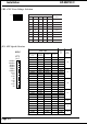
3-2. System Memory Configuration
3-3. Device Connectors
3-4. External Modem Ring-in Power ON and Keyboard Power ON
Functions (KBPO)
Section 3-1
Configure Jumpers
We design this motherboard with the fewest jumpers to make your install fast and
easy.
The following will describe all of the jumpers that you are required to set before
moving on to step 3-2.
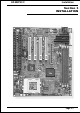
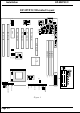
Note: The jumpers as depicted as shown (Figure 1) in their correct physical
orientation.
J7 WOL (Wake On Lan) Connector
Reserved for NIC (Network Interface Card) to
Wake the System.
1-2 - Run Mode (Default)
2-3 - Clear CMOS (momentarily)
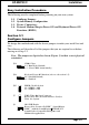
JP1 CMOS Clear
1
3
J8 SB-LINK Header
Reserved for Creative SB-LINK (Sound Blaster
LINK ) with the Sound Blaster AWE64D PCI
Sound Card to Compatible DOS games and
M ultimedia applications.
TM
TM
JP4
Disabled(Default)
Enabled
Keyboard Power-ON function (refer to the section 3-5)
1-2 -
2-3 -
3
1
JP5 DIMM Clock Selection
1-2 - DIMM = AGP
2-3 - DIMM = CPU
3
1