
User`s manual

BIOS
Page 4-11
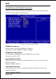
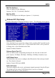
Onboard IDE Device Setup
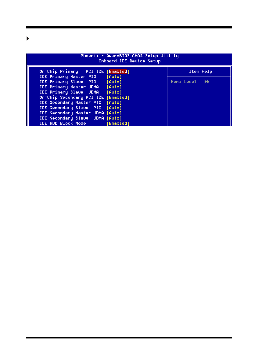
Scroll to Onboard IDE Device Setup and press <Enter>. The following screen appears:
On-Chip Primary PCI IDE
The integrated peripheral controller contains an IDE interface with support for
two IDE channels. Select Enabled (default) to activate each channel separately.
Options: Enabled, Disabled.
IDE Primary/Secondary Master/Slave PIO
The four IDE PIO (Programmed Input/Output) fields let you set a PIO mode (0-
4) for each of the four IDE devices that the onboard IDE interface supports.
Modes 0 through 4 provide successively increased performance. In Auto mode,
the system automatically determines the best mode for each device. The default
is Auto. Options: Auto, Mode 0 ~ 4.
IDE Primary/Secondary Master/Slave UDMA
This allows you to select the mode of operation for the Ultra DMA-33/66/100
implementation is possible only if your IDE hard drive supports it and the
operating environment includes a DMA driver (Windows 95 OSR2 or a third-
party IDE bus master driver). If your hard drive and your system software both
support Ultra DMA-33/66/100, select Auto to enable UDMA mode by BIOS or
you can select mode by manual.
Options: Auto, Disabled.
IDE HDD Block Mode
IDE Block Mode allows the controller to access blocks of sectors rather than a
single sector at a time. The default is Enabled.
Enabled: Enable IDE HDD Block Mode. Provides higher HDD transfer rates.
Disabled: Disable IDE HDD Block Mode.