
User`s manual


Installation
Page 3-6
Section 3-3
System RIMM Memory Module Configuration
Memory Layout
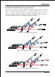
The board supports two channels (2) 232-pin RIMMs (Rambus Interface Memory
Module) as shown in Figure 7. The RIMMs can be RIMM and C-RIMM
(Continuity RIMM) only. RIMM modules have Rambus channel signals as their
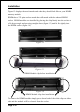
memory interface. A RIMM module may contain up to a maximum of 16 RDRAM
devices. All RDRAM devices on a RIMM must have the same timing
characteristics. Empty RIMM sockets must be populated with continuity modules
(C-RIMM). These modules have no memory on them and are used to propagate the
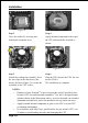
channel to the next RIMM socket. Figure 9, 10 & 11 provide a general diagram of
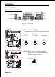
a RIMM module and installations of RIMM/C-RIMM modules. The board must
be populated 2 RIMM modules at the same time, that will boot-up the
system.
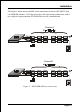
! The board supports a maximum of 16 devices on a RDRAM channel.
A Channel is defined as the two RIMM Slots on the motherboard added
together. Thus the motherboard has two channel. See Figure 7 for two
channel RDRAM interconnections.
! No support for EDO/SDRAM/DDR DIMM Modules.
! The board supports 32-bit RDRAM configurations.
! The RIMM modules and continuity RIMM (C-RIMM) spec. For more
detailed RIMM Modules spec. information you may visit the following
Web Site: http//www.rimm.com.
! Direct Rambus Channel operating at a clock rate of 400/533MHz which
enables a data rate of 800/1066MHz (data is clocked on both clock edges).
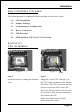
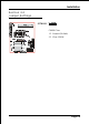
RIMM 1 (Channel A)
RIMM 2 (Channel B)
RIMM Module
and C-RIMM in
socket
Figure 7