User’s Manual nVIDIA nForce 2 Ultra 400 mainboard nForce2 for AMD Socket A processor TRADEMARK All products and company names are trademarks or registered trademarks of their respective holders. These specifications are subject to change without notice. 60000028PRO10 Manual Revision 1.
DISCLAIMER OF WARRANTIES: THERE ARE NO WARRANTIES WHICH EXTEND BEYOND THE DESCRIPTION ON THE FACE OF THE MANUFACTURER LIMITED WARRANTY. THE MANUFACTURER EXPRESSLY EXCLUDES ALL OTHER WARRANTIES, EXPRESS OR IMPLIED, REGARDING ITS PRODUCTS; INCLUDING ANY IMPLIED WARRANTIES OF MERCHANTABILITY, FITNESS FOR A PARTICULAR PURPOSE OR NONINFRINGEMENT.
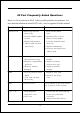
80 Port Frequently Asked Questions Below is a list of some basic POST Codes, possible problems and solutions. For more detailed information about POST Codes, refer to Appendix D in this manual. P O ST C O D E P r o bl e m So l uti o n FFh o r CFh 1 .B IO S c hip inse rte d 1 . Re inse rt the B IO S inc o rre c tly c hip 2 . Inc o rre c t BIO S update ve rsio n 3 . M ainbo ard pro ble m 4 . Add-o n c ard inse rte d inc o rre c tly. 2 .
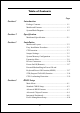
Table of Contents Page Section 1 Introduction Package Contents ...................................................... 1- 1 Mainboard Features ................................................... 1- 2 System Block Diagram ............................................... 1- 5 Section 2 Specification Mainboard Specification ............................................ 2- 1 Section 3 Installation Mainboard Layout ..................................................... 3- 2 Easy Installation Procedure ........
PNP/PCI Configuration .............................................. 4- 16 PC Health Status ........................................................ 4- 18 Power BIOS Features ................................................. 4- 19 Defaults Menu ........................................................... 4- 20 Supervisor/User Password Setting ............................ 4- 21 Exit Selecting ..............................................................
Page Left Blank vi
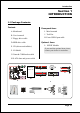
Introduction Section 1 INTRODUCTION 1-1 Package Contents Contents Powerpack items A. Mainboard I. Mini heatsink B. User’s manual J. Tool Pen K. Extra USB2.0 port cable C. Floppy drive cable Optional Items D. HDD drive cable L. S/PDIF Module E. CD (drivers and utilities) If you need the optional item, please contact your dealer for assistance. F. I/O Shield G. Game & COM bracket cable H.
Introduction 1-2 Mainboard Features Brief Introduction 2 AthlonTM Processor The AMD AthlonTM is a seventh-generation micro architecture with an integrated L2 cache, which is powerful enough to support the bandwidth requirements of a large range of applications, hardware, graphics, and memory technologies. For more information about all the new features AthlonTM Processor deliver, check out the AMD website at http://www.amd.
Introduction 2 GbE LAN This mainboard is optionally mounted with a Gigabit ethernet LAN chipset. The new Gigabit Ethernet LAN allows data transmission at 1,000 megabits per second (Mbps), which runs 10 times faster than conventional 10/100BASE-T Ethernet LANs. 2 Serial ATA Support Serial ATA, an evolutionary replacement for Parallel ATA IDE storage interface .Increases the peak data transfer speed up to 150MB/sec and allows future enhancements to the computing platform.
Introduction Special Features & 80 Port An onboard LED-display trouble-shooting device, facilitating user to detect boot-up problems. & NVIDIA Firewall The NVIDIA Firewall is a high performance, “hardware-optimized” firewall offering enhanced reliability and protection at the end-point. & QuickSPDIF On board SPDIF-out connector for quick connection to multi-channel speakers.
Introduction 1-3 System Block Diagram Page 1-5
Introduction Page 1-6
Specification Section 2 SPECIFICATION Mainboard Specification Processor Supports 462-pin SocketA for AMD Athlon XP and Barton processors with 266/333/400MHz Front Side Bus - Athlon XP (1500+ to 3000+) with 266/333MHz Front Side Bus, - Barton (2500+ to 3200+) with 333/400MHz Front Side Bus Chipset nVidia AGPset : nForce2 Ultra 400 + Gigabit MCP Main Memory Three 184-pin DDR DIMM sockets for 64-bit, Unbuffered, Single/Doubleside and DDR-266/333/400 DIMMs Supports 128-bit dual channel memory architect
Specification S-ATA --> Integrated Serial ATA controller from Silicon Image SiI3114 (Optional) for 4 ports solution with RAID 0, 1 ,10, 5 and support up to 150MB/sec transfer rate For more detailed information about SiI3114, refer to user’s manual in the bundled CD.
Specification One S/PDIF-Out Optical One Serial port One RJ45 LAN connector Four USB2.0 ports Six Audio jacks ) Onboard connector and pin-header One floppy drive connector Two ATA-133 IDE connectors Four extra USB2.
Specification Other Features Magic Health – A quick “dashboard” display at POST to show hardware status. Helps to detect faults early. EZ Boot – An easy way let end-user can choose to boot from hard drive, CD-ROM, floppy, … KBPO – Keyboard power on, turn on the computer from keyboard Supports NVIDIA Personal Firwall Function under Windows 2000/XP For more detailed information about NVIDIA Firewall, refer to user’s manual in the bundled CD.
Installation Section 3 INSTALLATION Note: Depending on the model you purchased, some components are optional and may not be available.
Installation Mainboard Layout Note: Depending on the model you purchased, some components are optional and may not be available.
Installation Easy Installation Procedure The following must be completed before powering on your new system: 3-1. CPU Installation 3-2. Jumper Settings 3-3. System Memory Configuration 3-4. Expansion Slots 3-5. Device Connectors 3-1 CPU Installation CPU Insertion: (use AMD AthlonTM as reference) Step 1 Open the socket by raising the actuation lever. Step 2 Insert the processor.
Installation Step 3 Close the socket by lowering and locking the actuation lever. Step 4 Thermal compound and qualified heatsink recommended by AMD are a must to avoid CPU overheat damage. For more information about installing your CPU, please refer to the AMD website article “Socket A AMD processor and Heatsink Installation Guide” http://www.amd.com/products/cpg/athlon/pdf/23986.pdf.
Installation 3-2 Jumper Settings JCMOS: Clear CMOS data Jumper If the CMOS data becomes corrupted or you forgot the supervisor or user password, clear the CMOS data to reconfigure the system back to the default values stored in the ROM BIOS. 1 Settings: 1-2: Normal (Default) 2-3: Clear CMOS To CMOS Clear data, please follow the steps below. 1. Turn off the system. 2. Change the jumper from “1-2” to “2-3” position for a few seconds. 3. Replace the jumper on to the “1-2” position. 4.
Installation 3-3 System Memory Configuration Memory Layout The mainboard accommodates three PC1600/2100/2700/3200 184-pin DIMMs (Dual Inline Memory Modules): • Supports up to 3.
Installation DIMM Module Installation Figure 7 displays the notch on the DDR DIMM memory module. DIMMs have 184 pins and one notch that matches with the DDR DIMM socket. DIMM modules are installed by placing the chip firmly into the socket and pressing straight down as shown in figure 8 until the white clips close and the module fits tightly into the DIMM socket (figure 9). CENTER KEY ZONE (2.
Installation 3-4 Expansion Slots AGP Slot The mainboard is equipped with an AGP slot. Make sure you install a card that supports the 1.5V specification. AGP Slot PCI Slots PCI Slots The mainboard is equipped with 6 PCI slots. Installing an Expansion Card The steps below assume that the mainboard is already installed in the system chassis. 1. Make sure the PC and all other peripheral devices connected to its has been powered down. 2. Disconnect all power cords and cables. 3.
Installation AGP Card Installation Caution 1. AGP card component is blocked by DIMM socket lock. 2. AGP slot clicker is not locked. 3. AGP card edge connector is not inserted properly. 1. AGP card component is not blocked by DIMM socket lock. 2. AGP slot clicker is locked. 3. AGP card edge connector is inserted properly. 1. AGP slot clicker is not locked. 2. AGP card edge connector is not inserted properly. 1. AGP slot clicker is locked. 2. AGP card edge connector is inserted properly.
Installation 3-5 Device Connectors The I/O back panel for this mainboard is shown below. When installing the mainboard into the computer case, use the bundled I/O shield to protect this back panel. RJ45 LAN Parallel Port Line-in (Light Blue) Side stereo-out (Gray) Front stereo-out (Lime) Rear stereo-out (Black) Mic-in (Pink) Center&Subwoofer (Orange) PS/2 Mouse PS/2 Keyboard S/PDIF-out S/PDIF-out COM1 Coaxial Jack Optical USB2.
Installation FDD: Floppy Controller Connector This mainboard connects floppy disk drive. IDE1/IDE2:Ultra DMA-100/133 Primary/Secondary IDE Connector IDE1IDE2 This mainboard is equipped with 2 IDE connectors to support up to 4 ATA-133 IDE drives. It supports PIO and DMA mode operations for maximum data transfer rate of 133MB/sec per channel. FDD 34 33 40 When using two IDE drives, one must be set to 39 Master mode and the other to Slave mode.
Installation CFPA: Front Panel Audio Connector When the jumpers are removed this connector can be used for front panel audio. The front panel phone jack should have “normal close” switch. Without phone plug inserted, the rear panel audio is enabled. With phone plug inserted, the rear panel audio will be disabled.
Installation SPDIF: Sony/Philips Digital InterFace connector This connector links digital audio between the mainboard and your audio devices, such as CD player, sampler or DAT recorder. It allows the digital transmission of audio data in S/PDIF format. SPDIF_IN VCC 5 1 6 2 NC GND SPDIF_OUT GAME1: Game/MIDI connector This port works well with any application that is compatible with the standard PC joystick.
Installation SATA1 / SATA2: Serial ATA Connectors SATA3 / SATA4 / SATA5 / SATA6 (Optional): Serial ATA Connectors from Silicon Image SiI3114 chip. These connectors enable you to connect Serial ATA devices that conform to the Serial ATA specification. SATA2 1 SATA5 SATA6 SATA3 SATA4 GND B+ BA- A+ GND GND C1394-1 / C1394-2 : 400Mbps 1394a (FireWire) Connectors C1394-1 and C1394-2 enable you to connect two IEEE 1394 ports for use with external devices that conform to the IEEE 1394 specification.
Installation CUSB3/CUSB4: USB 2.0 ports USB2.0 allows data transfer speed up to 480Mbps. This mainboard includes 4 additional USB2.0 ports, identified by two 10-pin connector. If you wish to use the additional USB ports, install the card-edge bracket to the system chassis then insert its cables to this 10-pin connector. CUSB3 CUSB4 CAUTION ! Please make sure the USB cable has the same pin assignment. A different pin assignment may cause damage to the system.
Installation CFP: Front Panel Connector HD_LED This LED will light up whenever the hard drive is being accessed. PWR_LED This connects to the power button of the system chassis CFP CIR RST This switch allows you to reboot without having to power off the system thus prolonging the life of the power supply or system. PW_ON This is connected to the power button on the case. To use the Soft-Off by PWR-BTTN feature, refer to the Power Management Setup in the BIOS setup section of this manual.
Installation 3-6 Power-On/Off (Remote) This board has a 20-pin ATX and a 4-pin ATX12V power supply connector to support power supplies with Remote On/Off feature. The 4-pin ATX12V connector must be plugged in for the system to operate safely. The chassis power button should be connected to the mainboard front panel PW_ON header (Figure 15).
Installation 3-8 ACPI S3 (Suspend To RAM) Function This mainboard supports the STR (Suspend To RAM) power management scheme by maintaining the appropriate power states in the DDR SDRAM interface signals. The power source to the DDR SDRAM is kept active during STR (ACPI S3). Advanced Configuration Power Interface (ACPI) provides many Energy Saving Features for operating systems that support Instant ON and QuickStartTM function. 1. To enable STR functionality to save system power : a.
Installation 3-9 CPU Overheating Protection This mainboard is equipped with CPU Overheating Protection. It will automatically shutdown the system when CPU temperature reaches approximately 110°C to prevent long term damage to the CPU. When this happens, the speaker produces a sustained beep sound and the system will not be able to power on. This protection is designed through hardware and no BIOS setup is required.
Installation Page 3-20
BIOS Section 4 BIOS SETUP Main Menu The ROM BIOS contains a built-in Setup program which allows user to modify the basic system configuration and hardware parameters. The modified data is stored in a battery-backed CMOS, so that data will be retained even when the power is turned off. In general, the information saved in the CMOS RAM will stay unchanged unless there is a configuration change in the system, such as hard drive replacement or a device is added.
BIOS The main menu displays all the major selection items. Select the item you need to reconfigure. The selection is made by moving the cursor (press any direction (arrow key ) to the item and pressing the ‘Enter’ key. An on-line help message is displayed at the bottom of the screen as the cursor is moved to various items which provides a better understanding of each function. When a selection is made, the menu of the selected item will appear so that the user can modify associated configuration parameters.
BIOS 4-2 Advanced BIOS Features Selecting the “ADVANCED BIOS FEATURES” option in the CMOS SETUP UTILITY menu allows users to change system related parameters in the displayed menu. This menu shows all of the manufacturer’s default values for the board. Pressing the [F1] key displays a help message for the selected item. Figure 3: BIOS Features Setup Removable Device / Hard Disk / CD-ROM / Network Boot Priority This item allows you to select the removable device/hard disk/CD-ROM/network boot priority.
BIOS Boot Up Floppy Seek If this item is enabled, it checks the size of the floppy disk drives at start-up time. You don’t need to enable this item unless you have a legacy diskette drive with 360K capacity. Options: Enabled, Disabled. Security Option This category allows you to limit access to the System and Setup, or just to Setup. The default is Setup. System: The system will not boot and access to Setup will be denied unless the correct password is entered at the prompt.
BIOS System Performance This item will help you to configure your system performance, selecting higher performance may cause instability. Options: Optimal, Aggressive, Turbo, Expert. CPU Clock Ratio Use this item to select a multiplier to set the CPU frequency. See FSB Frequency item below for explanation. FSB Frequency Enables you to increment the CPU’s clock generator at 1 MHz step. This works together with CPU Clock Ratio (above) to set the CPU operating frequency.
BIOS Memory Timings For setting DRAM Timing. Options: Optimal, Aggressive, Turbo, Expert. T (RAS) This item specifies the number of clock cycles needed after a bank active command before a precharge can occur (sets the minimum RAS pulse width.). Options: 1 ~ 15. T (RCD) This item sets the timing parameters for the system memory such as the CAS (Column Address Strobe) and RAS (Row Address Strobe). Options: 1 ~ 7.
BIOS AGP Aperture Size (MB) This item defines the size of the aperture if you use an AGP graphics adapter. It refers to a section of the PCI memory address range used for graphics memory. Options: 32, 64, 128, 256, 512 MB. AGP Frequency This item allows you to select the AGP frequency. Options: Auto, 90MHz, 93MHz, 95MHz, 97MHz, 100MHz, 50MHz ~87MHz in 1MHz increments. AGP 8X Support Enables AGP 8X supports. Options: Disabled, Enabled.
BIOS 4-4 Integrated Peripherals Figure 5: Integrated Peripherals Init Display First This item is used to select whether to initialize the AGP or PCI first when the system boots. Options: PCI Slot, Onboard/AGP. IDE Function Setup Scroll to IDE Function Setup and press .
BIOS OnChip IDE Channel 0/1, OnChip Serial-ATA The mainboard supports two channel of ordinary IDE interface and one channel of serial ATA interface. Select “Enabled” to activate each channel separately. Note: If you do not use the onboard IDE connector, then set the Onboard Primary (Secondary) PCI IDE to “Disabled”. Primary/Secondary Master/Slave UDMA Select the mode of operation for the IDE drive.
BIOS Onboard Device Scroll to Onboard Device and press . The following screen appears: Onchip USB Enables the USB controller. Options: Disabled, V1.1+V2.0, V1.1. USB KB/Storage Support Enable/Disable support for USB keyboard/Storage under DOS. Options: Enabled, Disabled. USB Mouse Support Enable/Disable support for USB mouse under DOS. Options: Enabled, Disabled. AC97 Audio This item allows you disable the chipset on-chip AC97 Audio. Options: Auto, Disabled.
BIOS Onboard Debug LED Enables the onboard Debug LED feature. Options: Enabled, Disabled. Onboard I/O Chip Setup Scroll to Onboard I/O Chip Setup and press . The following screen appears: POWER ON Function Enables computer power on by keyboard, mouse, or hotkey activity. Password: Requires you to enter a password when using the keyboard to power on. Set the password in the next field “KB Power ON Password.” Hot KEY: (default) Enables you to use a hot key combination to power on the computer.
BIOS Hot Key Power ON Enables you to set a hot key combination to be used for powering on the system. The default is Ctrl-F1. Options: Ctrl+F1 ~ Ctrl+F12. Onboard FDC Controller Select “Enabled” if you wish to use onboard floppy disk controller (FDC). If you install an external FDC or the system has no floppy drive, select “Disabled “in this field. Options: Enabled, Disabled. Onboard Serial Port 1/2 Select an address and corresponding interrupt for the first and second serial ports.
BIOS Parallel Port Mode This field allows the user to select the parallel port mode. Options: SPP, EPP, ECP, ECP+EPP. EPP Mode Select This field allows the user to select the EPP mode for parallel port mode. Options: EPP1.9, EPP1.7. ECP Mode USE DMA This field allows the user to select DMA1 or DMA3 for the ECP mode. Options: DMA1, DMA3. Game Port Address Select an address for the Game port. Options: 201, 209, Disabled. Midi Port Address Select an address for the Midi port.
BIOS 4-5 Power Management Setup Choose the “POWER MANAGEMENT SETUP” in the CMOS SETUP UTILITY to display the following screen. This menu allows the user to modify the power management parameters and IRQ signals. In general, these parameters should not be changed unless it’s absolutely necessary. Figure 6: Power Management ACPI Function Enables the ACPI Function. Options: Enabled, Disabled. ACPI Suspend Type This item allows you to select S1(Power-On-Suspend) or S3(Suspend-To-RAM) function.
BIOS Video Off Method This option allows you to select how the video will be disabled by the power management. The default is V/H Sync + Blank V/H Sync + Blank: System turns off vertical and horizontal synchronization ports and writes blanks to the video buffer. DPMS Support: Select this option if your monitor supports the Display Power Management Signaling (DPMS) standard of the Video Electronics Standards Association (VESA).
BIOS PwerOn After Pwr-Fail This item enables your computer to automatically restart or return to its last operating status after power returns from a power failure. Off: The system stays off after a power failure. Former-Sts: The system returns to the state it was in just prior to the power failure. 4-6 PNP/PCI Configuration This page lets the user to modify the PCI IRQ signals when various PCI cards are inserted. WARNING: Conflicting IRQ’s may cause system unable to locate certain devices.
BIOS PCI/VGA Palette Snoop This item is designed to overcome problems that may be caused by some nonstandard VGA cards. Options: Enabled, Disabled. Interrupt requests are shared as shown below: INT A AGP Slot INT B INT C AC97 V Slot 2 V V Slot 4 V Slot 5 V Onboard 1394 V Onboard LAN Onboard SiI3114 Onboard USB V V V Onboard USB V USB 2.
BIOS 4-7 PC Health Status Figure 8: PC Health Status Show PC Health in POST When this function is enabled the PC Health information is displayed during the POST (Power On Self Test). Options: Enabled, Disabled. Shutdown Temperature This is the temperature that the computer will turn off the power to combat the effects of an overheating system. (requires ACPI to be enabled in Power Management BIOS and ACPI compliant operating system.) The default is Disabled.
BIOS Chipset Voltage The voltage level of the Chipset. Dimm Voltage The voltage level of the DRAM. Battery Voltage The voltage level of the battery. Power Supply + 5V, 5V Standby The voltage level of the switching power supply. 4-8 POWER BIOS Features This page lets you adjust various parameters to obtain improved performance for overclocking. Warning: Overclocking requires expert knowledge and risks permanent damage to system components.
BIOS CPU Voltage Regulator This item allows you to set the CPU Vcore voltage. Options: 1.400V to 2.200V in 0.025V increments. AGP Voltage Regulator This item allows you to set the AGP slot voltage. Options: 1.5V to +1.8V in 1V increments. DIMM Voltage Regulator This item allows you to set the DIMM slot voltage. Options: 2.50V, 2.63V, 2.77V, 2.90V. Chipset Voltage Regulator This item allows you to set the chipset slot voltage. Options: 1.6V, 1.8V, 2.0V. Warning: Default chipset voltage is 1.6V.
BIOS 4-10 Supervisor/User Password Setting This function lets you set either Supervisor or User Password, or both, to prevent unauthorized changes to BIOS menus. supervisor password: full rights to enter and change options of the setup menus. user password: only enter but no rights to change options of the setup menus. When you select this function, the following message will appear at the center of the screen to assist you in creating a password.
BIOS 4-11 Exiting BIOS Save & Exit Setup Pressing on this item asks for confirmation: Save to CMOS and EXIT (Y/N)? Y Pressing “Y” stores the selections made in the menus in CMOS – a special section of memory that stays on after you turn your system off. The next time you boot your computer, the BIOS configures your system according to the Setup selections stored in CMOS. After saving the values the system is restarted again.
S-ATA RAID Configuration Section 5 S-ATA RAID CONFIGURATION Introduction This section gives a brief introduction on the RAID-related background knowledge and a brief introduction on S-ATA RAID Host Controller. RAID Basics RAID (Redundant Array of Independent Disks) is a method of combining two hard disk drives into one logical unit. The advantage of an Array is to provide better performance or data fault tolerance.
S-ATA RAID Configuration RAID 0 (Striping) RAID 0 reads and writes sectors of data interleaved between multiple drives. If any disk member fails, it affects the entire array. The disk array data capacity is equal to the number of drive members times the capacity of the smallest member. The striping block size can be set from 4KB to 64KB. RAID 0 does not support fault tolerance. RAID 1 (Mirroring) RAID 1 writes duplicate data onto a pair of drives and reads both sets of data in parallel.
S-ATA RAID Configuration This mainboard is equipped with the following SATA RAID controllers: 1. Nvidia SATA from nForce2 Gigabit MCP chip (SATA1/ SATA2) 2. (Optional) Silicon Image SiI3114 controller (SATA3/ SATA4/SATA5/SATA6) Each of these controllers have their own unique RAID setup BIOS and software. Note: Before you proceed, identify which SATA controller your HDD drives are connected to in order to ensure a successful installation.
S-ATA RAID Configuration Optional - Silicon Image Sil3114 S-ATA RAID Features • RAID 0, 1, 5, 10 • Hot Spare and On-line Mirror Rebuilding • System GUI Monitoring Utility: - Displays/Logs/Alerts Users to Vital RAID Set Information - Manages RAID Set Functions (configures, rebuilds, etc.
S-ATA RAID Configuration Enable RAID Function For any RAID controller, the general procedure to enable RAID function are shown below: Note: If you are not installing O/S into the RAID disks, you may skip Step 2 & Step3. Step 1: Create RAID Array RAID arrays are created using the RAID controller’s BIOS utility. NVIDIA nForce2 MCP Power-on the system and wait for the following screen to appear. Press the ”F10” key to enter its BIOS configuration utility.
S-ATA RAID Configuration (Optional) Silicon Image Sil3114 Wait for the following message to appear during boot-up: Press or F4 to enter RAID utility. An easy-to-use screen will appear with the following choices in the top left: Create RAID Set Delete RAID Set Rebuild RAID Set Resolve Conflicts Low Level Format Logical Drive Info Refer to Appendix C-2 for details about creating RAID array using this utility. Step 2: Prepare driver floppy When installing Windows XP/2000/NT4.
S-ATA RAID Configuration 4. Insert a blank floppy into the A:drive 5. Click on the required driver to begin copy into the floppy Step 3: Install O/S into RAID disk Continue to install Windows XP/2000/NT4.0 as normal. When requested by Windows Setup for RAID driver, insert the floppy created earlier in Step 2. Step 4: Install Software utility for Windows After the O/S has been installed, you may install the RAID driver and software.
S-ATA RAID Configuration Page 5-8
Drivers Installation Section 6 DRIVER INSTALLATION Easy Driver Installation (Optional) Insert the bundled CD-disk, the main menu screen will appear. The main menu displays buttons that link you to the supported drivers, utilities and software. Step 1 : Click “NVIDIA NFORCE Driver” to install chipset driver. Step 2 : Click “AC’97 AUDIO Driver” to install audio driver. Step 3 : Click “USB 2.0 Driver” to install USB 2.0 driver.
Drivers Installation Realtek Sound Manager Quick Guide Introduction To obtain the best performance from your audio system, run the "Sound Manager" utility to adjust the settings to suit your needs. This section of the manual is intended to provide a quick user-guide to setup "Sound Manager". For more detailed information, refer to "Sound Manager manual" in the CD. 1. Right-click “Sound Effect” button on the task bar and select “Sound Manager”. Sound Effect : 2.
Drivers Installation Speaker Configuration: 3. This page displays the mainboards's phone jack function when a corresponding audio mode is selected. Figure 3 above shows the phone jack setup for 8 channel mode. HRTF Demo: 4. This page lets you test the HRTF 3D Positional Audio features.
Drivers Installation General: 5. This page displays information regarding the audio hardware and software. To remove "Sound Manager" icon from Windows Task bar, uncheck "Show icon in system tray". SPDIF: 6. This page shows S/PDIF-In and S/PDIF-Out function on your system. S/PDIF-In: a. Click "Auto Lock" to detect S/PDIF input and display its information. b.Check "Real-time S/PDIF-In monitor" to listen to the S/PDIF In signal through Line-out connector.
Drivers Installation This board is equipped with Jack Sensing capability. If an audio device is plugged into the wrong connector, a warning message will appear to remind users to check the connection. Connector Sensing: 7. Push "Start" button to start the sensing. Please remember to terminate all audio applications before starting the sensing. Connector Sensing: 8. EZ-Connection shows the result of the detection.
Drivers Installation Connector Sensing: 9. After closing EZ-Connector, this page will show the latest connector status as above.
Appendix Appendix A A-1 Realtek Media Player User’s Guide Realtek Media Player Platform H 4 A 5 D 6 06 - Reo Speedwagon 1 I 1 2 5 6 2 K 3 C H J 8 4 7 3 B 06-Reo Speedwagon - K 03:31 E G F Functional Descriptions A. Playback Windows Display Playback windows displays the following mode information: 1. Playback Time Display 2. Voice Cancellation Mode Display 3. Pitch Mode Display 4.
Appendix B. Playback Function Controls There are 8 selectable functions for the playback: 1. Volume control High/Low Adjustment Bar. 2. Pitch control 4-step High/Low Adjustment Bar. 3. Repeat mode Choice of Repeat, All Repeat, Random or No Repeat Mode. 4. Mute Mute On/Off Mode select. 5. Voice cancellation Voice Cancellation On/Off Mode select for Karaoke. 6. Surround mode A total of 26 Surround Sound mode select as shown in the table below.
Appendix D. Seeking bar Display Animated Playback Status E. Title/Play List Windows Display Currently Selected Title(s) F. Title/Play List Edit Controls There title/play list controls include “Add”, “Del”, “Clear”, “Load”, & “Store”. 1. Add Add to the Title/Play List. 2. Del Remove form the Title/Play List. 3. Clear Clear the Title/Play List. 4. Load Load Title/Play List. 5. Store Save Title/Play List. G. Title/Play List Scroll bar Scroll Up/Down the Title/Play List. H.
Appendix J. Platform Display Panel Controls The platform display panel control include “Minimize” & “Close”. 1. Minimize Minimize Platform Display Panel. 2. Close Close/Exit Platform Display Panel. K. Equalizer Control Panel The Equalizer Control Panel include “On/Off” & “Preset”. 1. On/Off Enable/Disable Equalizer. 2. Preset Clear Equalizer setting to default value.
Appendix Appendix B B-1 Update Your System BIOS Download the xxxxx.EXE file corresponding to your model from our website to an empty directory on your hard disk or floppy. Run the downloaded xxxxx.EXE file and it will self extract. Copy these extracted files to a bootable floppy disk. Note: The floppy disk should contain NO device drivers or other programs. 1. Type “A:\AWDFLASH and press Key. 2. You will see the following setup screen. 3. Please key in the xxxxx.bin BIOS file name. XXXX 4.
Appendix 5. Key in File Name to save previous BIOS to file. XXXX XXXXX xxxxx.bin xxxxx.bin 6. To confirm and proceed, please key in [Y] to start the programming. XXXX XXXXX xxxxx.bin xxxxx.bin 7. The BIOS update is finished. XXXX XXXXX xxxxx.
Appendix Appendix C C-1 NVIDIA RAID BIOS Utility Power-on the system and wait for the following screen to appear. Press the ”F10” key to enter its BIOS configuration utility. Using the Define a New Array Window If necessary, press the tab key to move from field to field until the appropriate field is highlighted. • Selecting the RAID Mode By default, this is set to Mirroring.
Appendix To designate a free disk to be used as a RAID array disk, 1) Tab to the Free Disks section. The first disk in the list is selected 2) Move it from the Free Disks block to the Array Disks block by pressing the rightarrow key (-> ). The first disk in the list is moved, and the next disk in the list is selected and ready to be moved. 3) Continue pressing the right-arrow key (-> ) until all the disks that you want to use as RAID array disks appear in the Array Disks block.
Appendix Use the arrow keys to select the array that you want to set up, then press Enter. The Array Detail window appears. The Array Detail window shows information about the array that you selected, such as Striping Block used, RAID Mode, Striping Width, Disk Model Name, and disk capacity. If you want to mark this disk as empty and wipe out all its contents then press C. At the prompt, press Y to wipe out all the data, otherwise press N.
Appendix C-2 Optional - Silicon Image Sil3114 RAID BIOS Utility To enter this BIOS utility, power on and wait for the following message to appear during boot-up: Press or F4 to enter RAID utility. An easy-to-use screen will appear with the following choices in the top left: Create RAID Set Delete RAID Set Rebuild RAID Set Resolve Conflicts Low Level Format Logical Drive Info Below this will be listed the drives currently installed on the system.
Appendix to both drives as a Mirrored set. If, however, the source disk does not have data already stored on it, there is no need for Disk Copy. 4. The utility will ask “Are You Sure?” before completing the configuration. Rebuild RAID Sets This is used to initiate the copying of data a from an existing drive to a replacement drive that has been installed in a RAID set after the failure of the members. Deleting RAID Sets 1. To remove one or more RAID sets, select “Delete RAID Set.” 2.
Appendix C-6
Appendix Appendix D D-1 POST CODES POST (hex) DESCRIPTION CFh C0h Test CMOS R/W functionality. Early chipset initialization: - Disable shadow RAM - Disable L2 cache (socket 7 or below) - Program basic chipset registers Detect memory - Auto-detection of DRAM size, type and ECC. - Auto-detection of L2 cache (socket 7 or below) Expand compressed BIOS code to DRAM Call chipset hook to copy BIOS back to E000 & F000 shadow RAM.
Appendix 18h 19-1Ah 1Bh 1Ch 1Dh 1Eh 1Fh 20h 21h 22h 23h 24-26h 27h 28h 29h 2A-2Ch 2Dh 2E-32h 33h 34-3Bh 3Ch 3Dh 3Eh 3Fh 40h 41h 42h D-2 Detect CPU information including brand, SMI type (Cyrix or Intel) and CPU level (586 or 686). Reserved Initial interrupts vector table. If no special specified, all H/W interrupts are directed to SPURIOUS_INT_HDLR & S/W interrupts to SPURIOUS_soft_HDLR. Reserved Initial EARLY_PM_INIT switch.
Appendix 43h 44h 45-46h 47h 48h 49h 4A-4Dh 4Eh 4Fh 50h 51h 52h 53-54h 55h 56h 57h 58h 59h 5Ah 5Bh 5Ch 5Dh 5E-5Fh 60h 61-64h 65h 66h 67h 68h 69h 6Ah 6Bh 6Ch 6Dh Test 8259 functionality. Reserved Reserved Initialize EISA slot Reserved 1. Calculate total memory by testing the last double word of each 64K page. 2. Program writes allocation for AMD K5 CPU. Reserved 1. Program MTRR of M1 CPU 2. Initialize L2 cache for P6 class CPU & program CPU with proper cacheable range. 3.
Appendix 6Eh 6Fh 70-72h 73h 74h 75h 76h 77h 78h-79h 7Ah 7B-7Eh 7Fh 80h-81h 82h 83h 84h 85h 86-92h 93h 94h 95h 96h FFh D-4 Reserved 1. Initialize floppy controller 2. Set up floppy related fields in 40:hardware. Reserved (Optional Feature) Enter AWDFLASH.EXE if : -AWDFLASH is found in floppy drive. -ALT+F2 is pressed Reserved Detect & install all IDE devices: HDD, LS120, ZIP, CDROM….. Reserved Detect serial ports & parallel ports. Reserved Detect & install co-processor Reserved 1.