
Specifications

Computer Architecture and Maintenance (G-Scheme-2014)
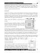
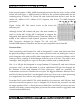
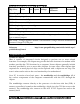
Socket 940 is used with the Socket 940 version of the AMD Athlon 64 FX, as well as
most AMD Opteron processors (see Figure). Motherboards using this socket support
only registered DDR SDRAM modules in dual-channel mode. Because the pin
arrangement is different, Socket 939 processors do not work in Socket 940, and vice
versa.
Figure. Socket 940. The cutout corner and triangle at the lower left
indicate pin 1.
Socket T
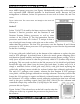
Socket T (LGA775) is used by the latest versions of the Intel
Pentium 4 Prescott processor and the Pentium D and
Pentium Extreme Edition processors, as well as some
versions of the Celeron D. The first-generation Prescott
processors used Socket 478. Socket T is unique in that it
uses a land grid array format, so the pins are on the socket,
rather than the processor. The first LGA processors were the Pentium II and Celeron
processors in 1997; in those processors LGA packaging was used for the chip mounted
on the Slot-1 cartridge.
LGA uses gold pads (called lands) on the bottom of the substrate to replace the pins
used in PGA packages. In socketed form, it allows for much greater clamping forces
and therefore greater stability and improved thermal transfer (better cooling). LGA is
really just a recycled version of what was previously called LCC (leadless chip carrier)
packaging. This was used way back on the 286 processor in '84, which had gold lands
around the edge only (there were far fewer pins back then). In other ways LGA is
simply a modified version of ball grid array (BGA), with gold lands replacing the
solder balls, making it more suitable for socketed (rather than soldered) applications.
The early LCC packages were ceramic, whereas the first Pentium II LGA packages
were plastic, with the package soldered to a cartridge substrate. These days (and for the
future) the LGA package is organic and directly socketed instead. On a technical level,
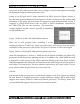
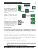
the Pentium 4 LGA chips combine several packaging technologies that have all been
used in the past, including organic land grid array (OLGA) for the substrate and
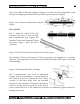
controlled collapse chip connection (C4) flip-chip for the actual
processor die (see Figure ).
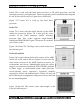
Figure. Socket T. The release lever on the left is used to raise the
clamp out of the way to permit the processor to be placed over
the contacts.
Prepared By – Prof. Manoj.kavedia (9860174297 – 9324258878 ) (www.kavediasir.yolasite.com)
34