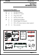
EP-6VBA A P entium ® II or P entium® III Pentium Pentium Slot1 Processor based AGP mainboar d (100/66MHz) mainboard Suppor ts PC-133 SDRAM Module Supports TRADEMARK All products and company names are trademarks or registered trademarks of their respective holders. These specifications are subject to change without notice. Manual Revision 4.
EP-6VBA Technical Support Services If you need additional information, help during installation or normal use of this product, please contact your retailer. If your retailer can not help, you may EMail us with any questions at the following address tech@epox.com Record your serial number before installing your EP-6VBA mainboard.
EP-6VBA User Notice No part of this product, including the product and software may be reproduced, transmitted, transcribed, stored in a retrieval system, or translated into any language in any form by any means without the express written permission of EPoX Computer Company (here in after referred to as EPoX) except documentation kept by the purchaser for backup purposes.
EP-6VBA Table of Contents Section 1 Introduction Components Checklist ....................................... 1-1 Overview Pentium® II or Pentium® III Processor ............... 1-2 S.E.C. Cartridge Terminology ........................... 1-3 Accelerated Graphics Port ................................ 1-4 Hardware Monitoring ........................................ 1-4 EP-6VBA Form-factor ...................................... 1-5 I/O Shield Connector .........................................
EP-6VBA Power Management Setup ................................. 4-11 PNP/PCI Configuration ..................................... 4-15 Load Setup Defaults .......................................... 4-17 Integrated Peripherals........................................ 4-17 Sensor and CPU Speed Setup ............................ 4-22 Change Supervisor or User Password ............... 4-24 IDE HDD Auto Detection .................................. 4-25 HDD Low Level Format....................................
EP-6VBA Page Left Blank
EP-6VBA Introduction Section 1 INTRODUCTION Components Checklist ü A. (1) EP-6VBA mainboard ü B. (1) EP-6VBA user’s manual ü C. (1) Floppy ribbon cable ü D. (1) Hard drive ribbon cables ü E. (1) Foldable Retention Module F. (1) Heatsink Support Unit (Optional) G. (1) PS/2 to AT keyboard connector adapter (optional) H.
Introduction EP-6VBA Overview Pentium® II or Pentium® III Processor The Pentium® II or Pentium® III Processor is the follow-on to the Pentium® Processor. The Pentium® II or Pentium® III Processor, like the Pentium® Pro processor, implements a Dynamic Execution micro-architecture -- a unique combination of multiple branch prediction, data flow analysis, and speculative execution.
EP-6VBA Introduction The entire enclosed product is called the Pentium® II or Pentium® III Processor. The packaging technology and each of the physical elements of the product are referred to using accurate technical descriptions. This allows clear reference to the products as just a processor. This is the model used in past packaging technologies like PGA, TCP, PQFP, DIP, etc. S.E.C.
Introduction EP-6VBA The L2 cache (TagRAM, PBSRAM) components keep standard industry names. The Pentium® II or Pentium® III Processor is the first product to utilize the S.E. C. cartridge technology and Slot 1 connector. Unless otherwise noted, any references to “Pentium® II Processor,” “Pentium® II or Pentium® III Processor/Slot 1 processor” or “Pentium® III Processor” will apply to both the Pentium® II Processor desktop processors. Accelerated Graphics Port (AGP or A.G.P.
EP-6VBA Introduction EP-6VBA Form-Factor The EP-6VBA is designed with ATX form factor - the new industry standard of chassis. ATX form factor is essentially a Baby-AT baseboard rotated 90 degrees within the chassis enclosure and a new mounting configuration for the power supply. With these changes the processor is relocated away from the expansion slots, allowing them all to hold full length add-in cards.
EP-6VBA Introduction I/O Shield Connector The EP-6VBA is equipped with an I/O back panel. Please use the appropriate I/ O shield (figure 3). Joystick/Midi port parallel port PS/2 Mouse USB port PS/2 KEYBOARD COM1 Figure 3: I/O back panel layout COM2 Speaker Power-On/Off (Remote) Line_in MIC The EP-6VBA has a single 20-pin connector for ATX power supplies.
EP-6VBA Introduction System Block Diagram Pentium II or Pentium III Processor 100/66MHz 66MHz PAC PCI Bridge and memory controller VT82C693 100/66MHz AMR Slot AC 97 VT82C686A I/O Bridge USB 0,1 USB 2,3 Figure 5: System Block Diagram Page 1-7
Introduction EP-6VBA Page Left Blank Page 1-8
EP-6VBA Features Section 2 FEATURES EP-6VBA Features: • EP-6VBA is based on the Pentium® II/III Processor operating at 266 ~ 550MHz on Slot1. The board is configured by an ESSJ (Easy-SettingSingle-Jumper) to match your CPU clock speed. • Designed with VIA Apollo Pro PCIset. • Supports up to 768MB of DRAM (minimum of 8 MB) on board (please see Section 3-2). • EP-6VBA will support Error Checking and Correcting (ECC) when using parity SDRAM memory modules.
Features EP-6VBA • Supports the (4) Universal Serial Bus (USB) Ports. The onboard VT82C686A chip provides the means for connecting PC peripherals such as; keyboards, joysticks, telephones, and modems. • Built-in ATX 20-pin power supply connector. • Software power-down when using Windows® 95/98. • Supports ring-in feature (remote power-on through external modem, allows system to be turned on remotely. • Resume by Alarm - Allows your system to turn on at a preselected time.
EP-6VBA Installation Section 3 INSTALLATION Page 3-1
EP-6VBA Installation EP-6VBA Detailed Layout Figure 1 Page 3-2
EP-6VBA Installation Easy Installation Procedure Easy Installation Procedure The following must be completed before powering on your new system: 3-1. 3-2. 3-3. 3-4. 3-5 Configure DIP Switch and Jumper to match your hardware System memory Configuration Install Pentium II or Pentium III Processor Device Connectors External Modem Ring-in Power ON and Keyboard Power ON Functions (KBPO) Section 3-1 Configure DIP Switch We design this motherboard with a DIP Switch to make your install fast and easy.
EP-6VBA Installation Section 3-2 System Memory Configuration Memory Layout The EP-6VBA supports (3) 168-pin DIMMs (Dual In-line Memory Module). The DIMMs can be either EDO (Enhanced Data Out) or SDRAM (Synchronized DRAM). • • • DIMM SDRAM may be 83MHz (12ns), 100MHz (10ns) or 125MHz (8ns) bus speed. If you use both 50ns and 60ns memory you must configure your BIOS to read 60ns. When using Synchronous DRAM we recommend using the 4 clock variety over the 2 clock.
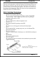
EP-6VBA Installation DIMM Module Installation Figure 3 displays the notch marks and what they should look like on your DIMM memory module. DIMMs have 168-pins and two notches that will match with the onboard DIMM socket. DIMM modules are installed by placing the chip firmly into the socket at a 90 degree angle and pressing straight down (figure 4) until it fits tightly into the DIMM socket (figure 5). LEFT KEY ZONE (UNBUFFERED) CENTER KEY ZONE (3.
EP-6VBA Installation Figure 5 DIMM Module clip after installation To remove the DIMM module simply press down both of the white clips on either side and the module will be released from the socket.
EP-6VBA Installation Section 3-3 Installing a Pentium II or Pentium III Processor The EP-6VBA uses the Single Edge Contact (SEC) slot for a Pentium ® II processor packaged in an SEC cartridge. The SEC slot is not compatible with other non-Pentium II processors. Please have ready the following list of components so that we may install the processor onto the motherboard. 1. 2. 3.
EP-6VBA Installation Now we need to secure the heatsink with the top half of the support (figure 9). Take the top piece of the support and slide it into the bottom fin (figure 9) on the heatsink and then push forward until it clips into the bottom base (figure 7) that is already there (figure 9). Figure 7 Figure 7 shows the layout of Slot 1 and the holes for mounting the Heatsink base piece (figure 6).
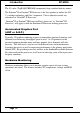
EP-6VBA Installation Section 3-4 Device Connectors Please install the motherboard into the chassis. Now that your motherboard is installed you are ready to connect all your connections (figure 10). parallel port PS/2 Mouse Joystic/Midi port USB port PS/2 KEYBOARD COM1 COM2 Figure 10 J2: Chassis Panel Connector • Power LED, Speaker, Reset J3: Turbo LED, HDD LED, IR Conn.
EP-6VBA Installation Device Connectors (continued) (This is connected to the power button on the case. Using the Soft-Off by Pwr-BTTN feature, you can choose either Instant Off (turns system off immediatly), or 4 sec delay (you need to hold the button down for 4 seconds before the system turns off). When the system is in 4 sec delay mode, there is a special feature to make the system to go into suspend mode when the button is pressed momentarily.
EP-6VBA Installation Section 3-5 External Modem Ring-in Power ON and Keyboard Power ON Functions (KBPO) On the basis of bounded functions in I/O chipset, the two serial ports are able to support the External Modem Ring-in Power ON function. Once users connect the external modem to COM1 or COM2, the EP-6VBA mainboard allows users to turn on their system through the remote and host's dial-up control.
Installation EP-6VBA Page Left Blank Page 3-12
EP-6VBA BIOS Section 4 AWARD BIOS SETUP BIOS Instructions Award’s ROM BIOS provides a built-in Setup program which allows user to modify the basic system configuration and hardware parameters. The modified data will be stored in a battery-backed CMOS, so that data will be retained even when the power is turned off. In general, the information saved in the CMOS RAM will stay unchanged unless there is a configuration change in the system, such as hard drive replacement or a device is added.
EP-6VBA BIOS The menu displays all the major selection items. Select the item you need to reconfigure. The selection is made by moving the cursor (press any direction key ) to the item and pressing the ‘Enter’ key. An on-line help message is displayed at the bottom of the screen as the cursor is moved to various items which provides a better understanding of each function. When a selection is made, the menu of the selected item will appear so that the user can modify associated configuration parameters.
EP-6VBA BIOS Note: The “Halt On:” field is used to determine when to halt the system by the BIOS if an error occurs. Note: Floppy 3 Mode support is a mode used to support a special 3.5” drive used in Japan. This is a 3.5” disk that stores only 1.2 MB, the default setting for this is disabled. 4-2 BIOS Features Setup Selecting the “BIOS FEATURES SETUP” option in the CMOS SETUP UTILITY menu allows users to change system related parameters in the displayed menu.
BIOS EP-6VBA Enabled: Activates automatically when the system boots up causing a warning message to appear when anything attempts to access the boot sector. Disabled: No warning message will appear when anything attempts to access the boot sector. Note: Many disk diagnostic programs that access the boot sector table can trigger the virus warning message. If you plan to run such a program, we recommend that you first disable the virus warning.
EP-6VBA BIOS Boot Sequence: This category determines which drive is searched first by the O/S (Operating System). The default is A,C,SCSI. The following is your list of options: [A, C, SCSI] - [C, A, SCSI] - [C, CD-ROM, A] - [CD-ROM, C, A] [D, A,CD-ROM],[E, A, CD-ROM] - [F, A, CD-ROM] - [SCSI, A, C] [SCSI C, A] - [C Only] Swap Floppy Drive: This will swap your physical drive letters A & B if you are using two floppy disks. The default is Disabled. Enabled: Floppy A & B will be swapped under the O/S.
EP-6VBA BIOS IDE HDD Block Mode: IDE Block Mode allows the controller to access blocks of sectors rather than a single sector at a time. The default is Enabled. Enabled: Enabled IDE HDD Block Mode. Provides higher HDD transfer rates. Disabled: Disable IDE HDD Block Mode. Gate A20 Option: This refers to the way the system addresses memory above 1MB (extended memory). The default is Fast. Normal: The A20 signal is controlled by the keyboard controller or chipset hardware.
EP-6VBA BIOS The default is 250. 250: 250 msec. 500: 500 msec. 750: 750 msec. 1000: 1000 msec. Security Option: This category allows you to limit access to the System and Setup, or just to Setup. The default is Setup. System: The system will not boot and the access to Setup will be denied if the correct password is not entered at the prompt. Setup: The system will boot; but the access to Setup will be denied if the incorrect password is not entered at the prompt.
EP-6VBA BIOS C8000 - CBFFF Shadow: CC000 - CFFFF Shadow: D0000 - D3FFF Shadow: D4000 - D7FFF Shadow: D8000 - DBFFF Shadow: DC000 - DFFFF Shadow: These categories determine whether ROMs from option cards will be copied into RAM. This will be in 16K byte or 32K byte units, and the size will depend on chipset of the option card. Enabled: Optional shadow is enabled. Disabled: Optional shadow is disabled.
EP-6VBA BIOS Bank 0/1, 2/3, 4/5 DRAM Timing: This value in this field is set by the system board manufacturer, depending on whether the board has paged DRAMs or EDO (extended data output) DRAMs. The Choice: Bank 0/1, 2/3, 4/5. SDRAM Cycle length: This setting defines the CAS timing parameter of the SDRAM in terms of clocks. The default is 3. 2: Provides faster memory performance. 3: Provides better memory compatibility.
BIOS EP-6VBA Read Around write: DRAM optimization feature: If a memory read is addressed to a location whose latest write is being held in a buffer contents, and the read is not sent to the DRAM. The Choice: Enabled, Disabled Concurrent PCI/Host: When disabled, CPU bus will be occupied during the entire PCI operation period.
EP-6VBA BIOS OnChip USB: Select Enabled if your system contains a Universal Serial Bus(USB) controller and you have a USB peripheral. USB Keyboard Support: This controls the activation status of an optional USB keyboard that may be attached. The default is disabled. Enabled: Enable USB keyboard support. Disabled: Disable USB keyboard support. OnChip Sound: Turn on/off onchip sound device. OnChip Modem: Turn on/off onchip software modem device.
EP-6VBA BIOS You can only change the content of Doze Mode, Standby Mode, and Suspend Mode when the Power Management is set to ‘User Define’. Power Management: Use this to select your Power Management selection. The default is User define. Disabled: The system operates in NORMAL conditions (Non-GREEN), and the Power Management function is disabled. Max. saving: Maximum power savings. Inactivity period is 1 minute in each mode. Min. saving: Minimum power savings. Inactivity period is 1 hour in each mode.
EP-6VBA BIOS MODEM Use IRQ: Name the interrupt request (IRQ) line assigned to the modem (if any) on your system. Activity of the selected IRQ always awakens the system. Default is IRQ 3. N/A: No IRQ is used. 4: IRQ 4 7: IRQ 7 10: IRQ 10 3: IRQ 3 5: IRQ 5 9: IRQ 9 11: IRQ 11 The EP-6VBA supports HDD Power Down, Doze and Standby power saving functions when using the Intel Pentium II Processor. The default is Disabled Soft-Off by PWR-BTTN: Use this to select your soft-off function.
BIOS EP-6VBA VGA: When set to On (default), any event occurring at a VGA port will awaken a system which has been powered down. LPT & COM: When set to On (default), any event occurring at a COM(serial)/LPT (printer) port will awaken a system which has been powered down. HDD & FDD: When set to On (default), any event occurring at a hard or floppy drive port will awaken a system which has been powered down.
EP-6VBA BIOS 4-5 PNP/PCI Configuration The PNP/PCI configuration program is for the user to modify the PCI/ISA IRQ signals when various PCI/ISA cards are inserted in the PCI or ISA slots. WARNING: Conflicting IRQ’s may cause the system to not find certain devices. ROM PCI/ISA BIOS(2A6LGPAA) PNP/PCI CONFIGURATION AWARD SOFTWARE, INC.
BIOS EP-6VBA Reset Configuration Data: This setting allows you to clear ESCD data.. The default is Disabled. Disabled: Normal Setting. Enabled: If you have plugged in some Legacy cards to the system and they were recorded into ESCD (Extended System Configuration Data), you can set this field to Enabled in order to clear ESCD. CPU to PCI Write Buffer: When enabled, up to four D words of data can be written to the PCI bus without interruting the CPU.
EP-6VBA BIOS 4-6 Load Setup Defaults The “LOAD SETUP DEFAULTS” function loads the system default data directly from ROM and initializes the associated hardware properly. This function will be necessary only when the system CMOS data is corrupted. 4-7 Integrated Peripherals ROM PCI/ISA BIOS(2A6LGPAA) INTEGRATEDPERIPHERALS AWARD SOFTWARE, INC.
BIOS EP-6VBA Onchip IDE Channel: The default value is Enabled. Enabled: Enables Onboard IDE primary port. Disabled: Disables Onboard IDE primary port. Onchip IDE Channel: The default is Enabled. Enabled: Enables Onboard IDE secondary port. Disabled: Disables Onboard IDE secondary port. Primary Master PIO: The default is Auto. Auto: BIOS will automatically detect the Onboard Primary Master PCI IDE HDD Accessing mode. Mode 0~4:Manually set the IDE Programmed interrupt mode.
EP-6VBA BIOS Primary Slave UDMA: This allows you to select the mode of operation for the hard drive. The default is Auto. Auto: The computer will select the optimal setting. Disabled: The hard drive will run in normal mode. Secondary Master UDMA: This allows you to select the mode of operation for the hard drive. The default is Auto. Auto: The computer will select the optimal setting. Disabled: The hard drive will run in normal mode.
BIOS EP-6VBA COM4: Enable Onboard Serial port 1 and address is 2E8H/IRQ3. Disabled: Disable Onboard Serial port 1. Onboard Serial Port 2: This field allows the user to configure the 2nd serial port. The default is Auto. AUTO: Enable Onboard Serial port 2 and address is Auto adjusted COM1: Enable Onboard Serial port 2 and address is 3F8H/IRQ4. COM2: Enable Onboard Serial port 2 and address is 2F8H/IRQ3. COM3: Enable Onboard Serial port 2 and address is 3E8H/IRQ4.
EP-6VBA BIOS Onboard Parallel Mode: This field allows the user to select the parallel port mode. The default is ECP+EPP. Normal: Standard mode. IBM PC/AT Compatible bidirectional parallel port. EPP: Enhanced Parallel Port mode. ECP: Extended Capabilities Port mode. EPP+ECP: ECP Mode & EPP Mode. ECP Mode USE DMA: This field allows the user to select DMA1 or DMA3 for the ECP mode. The default is DMA3. DMA1: This field selects the routing of DMA1 for the ECP mode.
EP-6VBA BIOS FM Port (388-38BH): Frequency modulation port at I/O port 388-38BH enabled/disabled. Game Port (200-207H): Built-in joystick port support disabled/enabled(default). 4-8 SENSOR AND CPU SPEED SETUP ROM PCI/ISA BIOS(2A6LGPAA) SENSOR AND CPU SPEED SETUP AWARD SOFTWARE, INC. Auto Detect DIMM/PCI Clk Spread Spectrum CPU Host Clock (CPU/PCI) DRAM Clock Is CPU Fan In Suspend : Enabled : Disabled : Default : Host Clock : Off Current CPU Temp. Current System Temp.
EP-6VBA BIOS CPU Host Clock (CPU/PCI): Allows the external clock to be modified depending upon what FSB has been selected. Should not be used to clock processor faster than it was designed for. (See page A-11). The default is Default. 66MHz FSB options: Default, 66.8, 68.5, 75, and 83MHz. 100MHz FSB options: Default, 100, 103, 112, and 133MHz. DRAM Clock Is: The item will synchronize/asynchronize DRAM operation clock. Host Clock: DRAM has same working clock with CPU host bus.
BIOS EP-6VBA 4-9 Change Supervisor or User Password To change the password, choose the “SUPERVISOR PASSWORD or USER PASSWORD” option from the CMOS SETUP UTILITY menu and press [Enter]. NOTE: Either “Setup” or “System” must be selected in the “Security Option” of the BIOS FEATURES SETUP menu. 1. If CMOS is corrupted or the option was not used, a default password stored in the ROM will be used.
EP-6VBA BIOS 4-10 IDE HDD Auto Detection The “IDE HDD auto detection” utility is a very useful tool, especially when you do not know which kind of hard disk type you are using. You can use this utility to detect the correct disk type installed in the system automatically. But now you can set HARD DISK TYPE to Auto in the STANDARD CMOS SETUP. You don’t need the “IDE HDD AUTO DETECTION” utility. The BIOS will Autodetect the hard disk size and model on display during POST.
EP-6VBA BIOS If user set his HDD to NORMAL mode, the maximum accessible HDD size will be 528 Megabytes even though its physical size may be greater than that! LBA (Logical Block Addressing) mode: A new HDD accessing method to overcome the 528 Megabyte bottleneck. The number of cylinders, heads & sectors shown in setup may not be the number physically contained in the HDD.
EP-6VBA BIOS Note: To support LBA or LARGE mode of HDDs, there must be some software involved. All the software is located in the Award HDD Service Routine (INT 13h). It may fail to access a HDD with LBA (LARGE) mode selected if you are running under an Operating System which replaces the whole INT 13h. UNIX operating systems do not support either LBA or LARGE and must utilize the Standard mode. UNIX can support drives larger than 528MB.
BIOS EP-6VBA Page Left Blank Page 4-28
EP-6VBA Appendix Appendix A A-1 MEMORY MAP Address Range [00000-7FFFF] [80000-9FBFF] [9FC00-9FFFF] installed [A0000-C7FFF] [C8000-DFFFF] ROMs [E0000-EEFFF] [EF000-EFFFF] [F0000-F7FFF] [F8000-FCFFF] [FD000-FDFFF] [FE000-FFFFF] Size 512K 127K 1K Description Conventional memory Extended Conventional memory Extended BIOS data area if PS/2 mouse is 160K 96K Available for Hi DOS memory Available for Hi DOS memory and adapter 60K 4K Available for UMB Video service routine for Monochrome & CGA adaptor BIOS
EP-6VBA Appendix [3B0-3BF] [3C0-3CF] [3D0-3DF] [3F0-3F7] [3F8-3FF] MONOCHROME & PARALLEL port adapter. EGA adapter. CGA adapter. FLOPPY DISK controller. SERIAL port 1. A-3 TIMER & DMA CHANNELS MAP TIMER MAP: TIMER Channel 0 TIMER Channel 1 TIMER Channel 2 DMA CHANNELS: DMA Channel 0 DMA Channel 1 DMA Channel 2 DMA Channel 3 DMA Channel 4 DMA Channel 5 DMA Channel 6 DMA Channel 7 System timer interrupt. DRAM REFRESH request. SPEAKER tone generator. Available. Onboard ECP (Option). FLOPPY DISK (SMC CHIP).
EP-6VBA 12 13 14 15 Appendix PS/2 Mouse. MATH coprocessor. Onboard HARD DISK (IDE1) channel. Onboard HARD DISK (IDE1) channel. A-5 RTC & CMOS RAM MAP RTC & CMOS: 00 Seconds. 01 Second alarm. 02 Minutes. 03 Minutes alarm. 04 Hours. 05 Hours alarm. 06 Day of week. 07 Day of month. 08 Month. 09 Year. 0A Status register A. 0B Status register B. 0C Status register C. 0D Status register D. 0E Diagnostic status byte. 0F Shutdown byte. 10 FLOPPY DISK drive type byte. 11 Reserve. 12 HARD DISK type byte.
Appendix EP-6VBA Page Left Blank A-4
EP-6VBA Appendix Appendix B B-1 POST CODES ISA POST codes are typically output to I/O port address 80h. POST (hex) DESCRIPTION 01-02 Reserved. C0 Turn off OEM specific cache, shadow. 03 1. Initialize EISA registers (EISA BIOS only). 2. Initialize all the standard devices with default values Standard devices includes. - DMA controller (8237). - Programmable Interrupt Controller (8259). - Programmable Interval Timer (8254). - RTC chip. 04 Reserved 05 1. Keyboard Controller Self-Test. 06 2.
Appendix 0C 0D 0E 0F 10 11 12-13 14 15 16 17 19 1A-1D 1E 1F-29 30 31 32 33-3B 3C 3D A-6 EP-6VBA Initialization of the BIOS Data Area. (40:ON - 40:FF) 1. Program some of the Chipset's value according to Setup. (Early Setup Value Program) 2. Measure CPU speed for display & decide the system clock speed. 3. Video initialization including Monochrome, CGA, EGA/VGA. If no display device found, the speaker will beep. 1. Test video RAM. (If Monochrome display device found) 2. Show messages including.
EP-6VBA 3E 3F-40 BF 41 42 43 45 44 45 46-4D 4E 4F 50 51 52 53 60 Appendix Try to turn on Level 2 cache. Note: Some chipset may need to turn on the L2 cache in this stage. But usually, the cache is turn on later in POST 61h. Reserved. 1. Program the rest of the Chipset's value according to Setup. (Later Setup Value Program) 2. If auto-configuration is enabled, program the chipset with pre-defined Values. Initialize floppy disk drive controller. Initialize Hard drive controller.
EP-6VBA Appendix 61 62 63 FF 1. Try to turn on Level 2 cache. Note: If L2 cache is already turned on in POST 3D, this part will be skipped. 2. Set the boot up speed according to Setup setting. 3. Last chance for Chipset initialization. 4. Last chance for Power Management initialization. (Green` BIOS only) 5. Show the system configuration table. 1. Setup daylight saving according to Setup value. 2. Program the NUM Lock, typematic rate & typematic speed according to Setup setting. 1.
EP-6VBA Appendix Appendix C NOTE: The "LOAD SETUP DEFAULTS" function loads the system default data directly from ROM and initializes the associated hardware properly. This function will be necessary when you accept this mainboard, or the system CMOS data is corrupted. ROM PCI/ISA BIOS(2A6LGPAA) CMOS SETUP UTILITY AWARD SOFTWARE, INC.
Appendix EP-6VBA Page Left Blank A-10
EP-6VBA Appendix Appendix D D-1 Sound Driver Quick Installation Guide Install windows 95/98 Sound Driver **Installation Notes: You must already have Windows 95/98 install on your computer. 1. Login windows 95/98, then click “My Computer” icon, “Control Panel” icon, and “System” icon. 2. Before the Driver install into windows 95/98, you will find a yellow question mark still exits the “Other Devices” of the “Device Manager” show in Figure 1-1 below.
EP-6VBA Appendix 3. Please remove the yellow question mark then click "refresh", windows will detect it's presence and display the following dialog. 4. Click "Next" button, it will find Floppy A: 5. Click "Other Locations¡K"button 6. Key-in the driver location (ex. D:\Audio\Win9x) then click "OK" button (You can use the "Browse" button to find the driver location; if you don't know where the driver is) 7. Click "Finish" button 8. The click "OK" button 9.
EP-6VBA Appendix D-2 AGP Driver Quick Installation Guide Install windows 95/98/NT V4.0 Driver **Installation Notes: 1. Before installing Windows 95 Driver, please do install Windows 95 OSR2.0 "USB SUPP.EXE" first (upgrades OS up to OSR2.1 level). 2. The Operation System(OS) and DirectX 5.0 or 6.0 must be installed into the system prior to installation. 3. Before installing Windows NT 4.0 Driver, please install "Microsoft service pack 3 or 4" First. 1. After Windows 9x or Windows NT V4.