Model No. ECTL09706.1 Serial No. Find the serial number in the location shown below. Write the serial number in the space above for reference. Serial Number Decal QUESTIONS? As a manufacturer, we are committed to providing complete customer satisfaction. If you have questions, or if parts are damaged or missing, please contact our customer service department directly. 1-888-936-4266 Mon.–Fri. 8h00 until 17h00 EST (excluding holidays). or e-mail us: customerservice@iconcanada.
TABLE OF CONTENTS IMPORTANT PRECAUTIONS . . . . . . . . . . . . . . . . . . . . . . . . . . . . . . . . . . . . . . . . . . . . . . . . . . . . . . . . . . . . . . . . .3 BEFORE YOU BEGIN . . . . . . . . . . . . . . . . . . . . . . . . . . . . . . . . . . . . . . . . . . . . . . . . . . . . . . . . . . . . . . . . . . . . . . .6 ASSEMBLY . . . . . . . . . . . . . . . . . . . . . . . . . . . . . . . . . . . . . . . . . . . . . . . . . . . . . . . . . . . . . . . . . . . . . . . . . . . . . . .
IMPORTANT PRECAUTIONS WARNING: To reduce the risk of burns, fire, electric shock, or injury to persons, read the following important precautions and information before operating the treadmill. 1. It is the responsibility of the owner to ensure that all users of this treadmill are adequately informed of all warnings and precautions. 12. Failure to use a properly functioning surge suppressor could result in damage to the control system of the treadmill.
21. Do not change the incline of the treadmill by placing objects under the treadmill. or other electric light or power circuits, or where it can fall into such power lines or circuits. When installing an outside antenna system, extreme care should be taken to keep from touching such power lines or circuits, as contact with them might be fatal. 22. When folding or moving the treadmill, make sure that the frame is held securely by the pin on the latch knob. 23.
Power Lines Ground Clamp Service Entrance Conductors Standoff Insulators Mast To External Antenna Terminal of Treadmill Service Entrance Equipment Power Service Grounding Electrode System (e.g. Interior Metal Water Pipe) Antenna Lead-in Wire Ground Wire Antenna Discharge Unit Ground Wire Ground Clamps Bonding Jumper Ground Clamps Optional Antenna Grounding Electrode Driven 8 Feet (2.44m) Into The Earth (If Required By Local Codes). See NEC Section 810–21 (f).
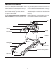
BEFORE YOU BEGIN Thank you for selecting the revolutionary EPIC™ VIEW 550 treadmill. The VIEW 550 treadmill offers an impressive selection of features designed to make your workouts at home more enjoyable and effective. And when you’re not exercising, the unique VIEW 550 treadmill can be folded up, requiring less than half the floor space of other treadmills. ing this manual, please see the front cover of this manual.
4 1/2” Bolt (78)–4 nsion Leg (106)–4 ASSEMBLY w (123)–2 Washe Assembly requires two persons. Set the treadmill in a cleared remove all packing materials. Do not 3/4”area Tek and Screw (58)–4 dispose of the packing materials until assembly is completed. 1/2” Silver Screw (48)–1 Note: The underside of the treadmill walking belt is coated with high-performance lubricant.
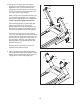
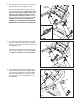
2. Identify the Left Upright (73) and the Right Upright (74). Hold the Right Upright near the Right Base Cover (77) as shown. Feed the Upright Wire Harness (75) up into the rectangular hole in the bottom of the Right Upright and out of the top of the Right Upright. 2 97 49 Gently pull up on the Upright Wire Harness (75) as you set the Right Upright (74) on the Base (83) inside the Right Base Cover (77). Be careful not to pinch the Upright Wire Harness.
4. With the help of a second person, hold the console assembly near the Uprights (73, 74). 4 Console Assembly Connect the Upright Wire Harness (75) to the Console Wire Harness (71). Make sure to connect the connectors properly (see the inset drawing). The connectors should slide together easily and snap into place. If they do not, turn one connector and try again. IF THE CONNECTORS ARE NOT CONNECTED PROPERLY, THE CONSOLE MAY BE DAMAGED WHEN THE POWER IS TURNED ON. 73 71 75 74 75 5.
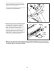
7. Slide the Right Upright Sleeve (96) up against the console assembly. Attach the Right Upright Sleeve with two 3/4" Screws (4). 7 Attach the Left Upright Sleeve (not shown) to the Left Upright (73) as described above. 73 4 96 4 8. Note the location of the 75 ohm antenna terminal and the audio/video input jack on the treadmill.
If you purchase the optional chest pulse sensor (see page 20), follow the steps below to install the receiver included with the chest pulse sensor. 1. Make sure that the power cord is unplugged. Remove the indicated 3/4" Screws (4) from the Pulse Receiver Cover (70) on the back of the Console Assembly (A). 1 A 70 4 2. Next, hold the receiver so the small cylinder is oriented as shown. Attach the receiver to the Pulse Receiver Cover (70) with the two included Small Screws (B). 2 B Cylinder 70 3.
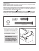
Before the personal television can be used, you must connect an antenna, a 75 ohm CATV cable, or a VCR to the 75 ohm antenna terminal on the treadmill frame. Note: No antenna, cable, or adapter is included. HOW TO CONNECT AN ANTENNA 300 Ohm Flat Wire Indoor Antenna 1. See the drawing near the bottom of this page. Connect the 300 ohm flat wire from the antenna to a 300 ohm to 75 ohm adapter. 1. Place a VHF antenna in the desired location.
OPERATION AND ADJUSTMENT THE PRE-LUBRICATED WALKING BELT Your treadmill features a walking belt coated with highperformance lubricant. IMPORTANT: Never apply silicone spray or other substances to the walking belt or the walking platform. Such substances will deteriorate the walking belt and cause excessive wear. HOW TO PLUG IN THE POWER CORD DANGER: Improper connection of the equipment-grounding conductor can result in an increased risk of electric shock.
CONSOLE DIAGRAM Note: If there is a sheet of clear plastic on the console, peel off the clear plastic. Key Clip FEATURES OF THE CONSOLE seven Performance programs. Each program automatically controls the speed and incline of the treadmill as it guides you through an effective workout. The treadmill console offers an impressive array of features designed to make your workouts more effective and enjoyable.
HOW TO TURN ON THE POWER 1 2 HOW TO USE THE MANUAL MODE Plug in the power cord (see page 13). Next, Reset locate the reset/off cirPosition cuit breaker on the treadmill frame near the power cord. Make sure that the circuit breaker is in the reset position. 1 Insert the key into the console. See HOW TO TURN ON THE POWER on this page. 2 Select the manual mode. Each time the key is inserted, the manual mode will be selected.
5 Select a display mode and follow your progress with the exercise information on the screen. 6 Measure your heart rate if desired. Note: If you use the handgrip pulse sensor and the optional chest pulse sensor at the same time, the display will not show your heart rate accurately. As you walk or run on the treadmill, the screen can display the following exercise information: • The elapsed time.
position to the right. Note: The program diagram can only be displayed when the television is in Console mode. To select the Console mode, press the TV button repeatedly until the word “Console” appears on the screen. HOW TO USE A PRESET PROGRAM 1 Insert the key into the console. See HOW TO TURN ON THE POWER on page 15. 2 When the first segment ends, the treadmill will automatically adjust to the speed and incline settings for the second segment. Select a preset program.
4 HOW TO OPERATE THE PERSONAL TELEVISION When either Volume (Vol) button is pressed, the volume level indicator will appear on the screen for a few seconds. IMPORTANT: Before operating the television, you must connect an antenna, a 75 ohm CATV cable, or a VCR to the 75 ohm antenna terminal on the treadmill, a VCR or DVD player to the three audio/video RCA jacks, or a personal audio/video player to the audio/video jack below the television on the console. See page 12 for instructions.
3 HOW TO USE THE INFORMATION MODE The console features an information mode that allows you to view treadmill usage information, select a system of measurement for the console, and turn on and turn off the demo mode. The information mode also allows you to adjust the settings of the television and to save channels into the television’s memory.
THE OPTIONAL CHEST PULSE SENSOR An optional chest pulse sensor offers hands-free operation as it monitors your heart rate during your workouts. To purchase the optional chest pulse sensor, call the toll-free telephone number on the front cover of this manual.
HOW TO FOLD AND MOVE THE TREADMILL HOW TO FOLD THE TREADMILL FOR STORAGE Before folding the treadmill, adjust the incline to the lowest position. If this is not done, the treadmill may become permanently damaged. Remove the key and unplug the power cord. CAUTION: You must be able to safely lift 45 pounds (20 kg) to raise, lower, or move the treadmill. 1. Hold the metal frame firmly in the location shown by the arrow at the right.
TROUBLESHOOTING Most treadmill problems can be solved by following the steps below. Find the symptom that applies, and follow the steps listed. If further assistance is needed, please see the front cover of this manual. PROBLEM: The power does not turn on SOLUTION: a. Make sure that the power cord is plugged into a surge suppressor, and that the surge suppressor is plugged into a properly grounded outlet (see page 13).
Next, locate the Reed Switch Clip (14) and the Magnet (12) on the left side of the Pulley (11). Turn the Pulley until the Magnet is aligned with the Reed Switch. Make sure that the gap between the Magnet and the Reed Switch is about 1/8". If necessary, loosen the indicated 3/4" Tek Screw (29), move the Reed Switch slightly, and then retighten the Screw. Then, reattach the hood, and run the treadmill for a few minutes to check for a correct speed reading.
PROBLEM: The incline of the treadmill does not change correctly SOLUTION: a. With the key in the console, press one of the Incline buttons. While the incline is changing, remove the key. After a few seconds, re-insert the key. The treadmill will automatically rise to the maximum incline level and then return to the minimum level. This will recalibrate the incline system.
CONDITIONING GUIDELINES WARNING: Before beginning this or any exercise program, consult your physician. This is especially important for individuals over the age of 35 or individuals with preexisting health problems. The pulse sensor is not a medical device. Various factors, including your movement, may affect the accuracy of heart rate readings. The sensor is intended only as an exercise aid in determining heart rate trends in general. The following guidelines will help you to plan your exercise program.
PART LIST—Model No. ECTL09706.1 R0107A To locate the parts listed below, see the EXPLODED DRAWING attached in the center of this manual. Key No. Qty. 1 2 3 4 5 6 7 8 9 10 11 12 13 14 15 16 17 18 19 20 21 22 23 24 25 26 27 28 29 30 31 32 33 34 35 36 37 38 39 40 41 42 43 44 45 46 47 48 49 2 2 8 70 2 1 2 5 2 2 1 1 8 1 2 2 2 2 2 1 1 1 1 1 1 1 1 1 5 2 1 2 4 1 1 1 1 11 1 1 1 2 1 1 4 2 1 1 1 Description Key No. Qty.
Key No. Qty. 99 100 101 102 103 104 105 106 107 108 109 110 111 112 113 114 1 1 1 1 1 1 2 1 1 1 1 1 2 1 1 4 Description Key No. Qty.
2 57 59 38 58 4 105 52 56 3 62 101 29 72 61 1 54 3 56 52 72 105 42 4 60 29 6 3 61 38 51 62 7 104 8 48 23 4 9 4 1 47 26 3 3 22 25 68 4 18 10 3 17 28 38 79 21 27 16 30 42 13 11 12 20 14 29 4 19 15 38 50 4 3 10 8 55 33 7 3 4 117 2 32 31 33 118 9 34 55 55 33 4 4 4 36 13 4 18 100 15 4 35 37 38 16 17 19 30 98 8 53 38 40 39 38 43 126 107 44 113 119 108 24 103 106 4 45 4 4 45 115 4 EXPLODED DRAWI
94 4 89 4 114 124 4 4 4 91 4 94 92 80 88 63 69 4 116 110 120 125 84 4 114 122 66 116 99 4 4 4 92 88 84 4 70 88 4 121 4 80 88 4 71 78 13 127 76 67 4 86 87 65 4 85 4 4 4 93 4 123 64 95 38 90 81 82 4 38 49 64 90 4 4 97 4 90 73 86 90 38 72 64 90 5 85 83 41 13 4 46 4 87 90 75 111 81 82 4 75 49 97 102 112 109 4 81 82 4 96 46 64 87 90 38 72 74 13 77 82 81 EXPLODED DRAWING—Model No. ECTL09706.
ORDERING REPLACEMENT PARTS To order replacement parts, please see the front cover of this manual. When ordering parts, be prepared to provide the following information: • the MODEL NUMBER of the product (ECTL09706.