NTC thermistors for temperature measurement SMD NTC thermistors, EIA case size 0805 (2012), standard series Series/Type: B574**V2/ B57620C5 Date: February 2019 © TDK Electronics AG 2019. Reproduction, publication and dissemination of this publication, enclosures hereto and the information contained therein without TDK Electronics' prior express consent is prohibited.
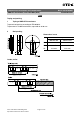
Temperature measurement and compensation B574**V2/ B57620C5 SMD NTC thermistors, case size 0805 (2012) Applications Temperature measurement and compensation Standard series Dimensional drawing Features Multilayer SMD NTC with inner electrodes Nickel barrier termination For temperature measurement up to 125 °C Excellent long-term aging stability in high temperature environment High mechanical robustness Short response time 100% Pb free UL approval (E69802) Options Alternative resistance ratings, resist
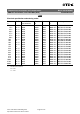
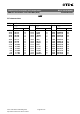
Temperature measurement and compensation B574**V2/ B57620C5 SMD NTC thermistors, case size 0805 (2012) Standard series Electrical specification and ordering codes R25 Ω 1.0 k 1.5 k 2.2 k 3.3 k 4.7 k 4.7 k 6.8 k 10 k 10 k 10 k 10 k 15 k 22 k 22 k 33 k 33 k 47 k 47 k 100 k 470 k 680 k ∆RR/RR % ±3, ±5 ±3, ±5 ±3, ±5 ±3, ±5 ±3, ±5 ±3, ±5 ±3, ±5 ±3, ±5 ±5 ±3, ±5 ±3, ±5 ±5 ±3, ±5 ±3, ±5 ±3, ±5 ±3, ±5 ±3, ±5 ±3, ±5 ±3, ±5 ±3, ±5 ±3, ±5 No.
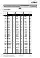
Temperature measurement and compensation B574**V2/ B57620C5 SMD NTC thermistors, case size 0805 (2012) Standard series Reliability data SMD NTC thermistors are tested in accordance with IEC 60068. The parts are mounted on a standardized PCB in accordance with IEC 60539-1.
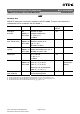
Temperature measurement and compensation B574**V2/ B57620C5 SMD NTC thermistors, case size 0805 (2012) Standard series R/T characteristics R/T No. T (°C) 1011 8500 8502 B25/100 = 3730 K B25/100 = 3650 K B25/100 = 4000 K RT/R25 α (%/K) RT/R25 α (%/K) RT/R25 α (%/K) 55.0 50.0 45.0 40.0 35.0 70.014 49.906 36.015 26.296 19.411 6.9 6.7 6.4 6.2 6.0 63.917 45.889 33.344 24.504 18.201 6.8 6.5 6.3 6.1 5.8 96.158 66.892 47.127 33.606 24.243 7.4 7.1 6.9 6.6 6.4 30.0 25.0 20.0 15.0 10.0 14.
Temperature measurement and compensation B574**V2/ B57620C5 SMD NTC thermistors, case size 0805 (2012) Standard series R/T characteristics R/T No. 8507 T (°C) B25/100 = 4480 K T (°C) RT/R25 α (%/K) 55.0 50.0 45.0 40.0 35.0 142.71 96.913 66.637 46.366 32.629 B25/100 = 4480 K T (°C) RT/R25 α (%/K) B25/100 = 4480 K RT/R25 α (%/K) 7.9 7.6 7.4 7.1 6.9 15.0 20.0 25.0 30.0 35.0 1.6492 1.2798 1.0000 0.78663 0.62277 5.1 5.0 4.9 4.7 4.6 85.0 90.0 95.0 100.0 105.0 0.081823 0.068589 0.057735 0.
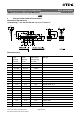
Temperature measurement and compensation B574**V2/ B57620C5 SMD NTC thermistors, case size 0805 (2012) Standard series Taping and packing 1 Taping of SMD NTC thermistors Tape and reel packing according to IEC 60286-3. Tape material: Cardboard or blister, tape width 8 ±0.30 mm 2 Reel packing Dimensions in mm 8-mm tape 180-mm reel 330-mm reel A 180 +0/ 3 330 +0/ 2.0 W1 8.4 +1.5/ 0 8.4 +1.5/ 0 W2 14.4 max. 14.4 max.
Temperature measurement and compensation B574**V2/ B57620C5 SMD NTC thermistors, case size 0805 (2012) Standard series Packing units for discrete chip Case size Chip thickness inch/mm 0402/1005 0603/1608 0805/2012 1206/3216 3 th 0.5 mm 0.8 mm 0.8 mm 1.2 mm 0.8 mm 1.2 mm Cardboard tape Blister tape W 8 mm 8 mm W 8 mm 8 mm 8 mm 8 mm 8 mm ∅ 180-mm reel ∅ 330-mm reel pcs. 10000 4000 2000/ 4000 3000 2000 4000 pcs.
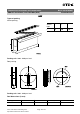
Temperature measurement and compensation B574**V2/ B57620C5 SMD NTC thermistors, case size 0805 (2012) 4 Standard series Taping of radial leaded NTC thermistors Dimensions and tolerances Lead spacing F = 2.5 mm and 5.0 mm (taping to IEC 60286-2) Dimensions (mm) w th d P0 P1 F ∆h ∆p W W0 W1 W2 H H0 H1 D0 t L L1 Lead spacing 2.5 mm 11.0 5.0 0.5/0.6 12.7 5.1 2.5 0 0 18.0 5.5 9.0 3.0 18.0 16.0 32.2 4.0 0.9 11.0 4.0 Lead spacing 5 mm 11.5 6.0 0.5/0.6 12.7 3.85 5.0 0 0 18.0 5.5 9.0 3.0 18.0 16.0 32.2 4.
Temperature measurement and compensation B574**V2/ B57620C5 SMD NTC thermistors, case size 0805 (2012) Standard series Types of packing Ammo packing Ammo type x y z I 80 240 210 Packing unit: 1000 - 2000 pcs./reel Reel packing Packing unit: 1000 - 2000 pcs./reel Reel dimensions (in mm) Reel type d f n w I 360 max. 31 ±1 approx. 45 54 max. Please read Cautions and warnings and Important notes at the end of this document.
Temperature measurement and compensation SMD NTC thermistors, case size 0805 (2012) B574**V2/ B57620C5 Standard series Cassette packing Packing unit: 1000 - 2000 pcs./cassette Bulk packing The components are packed in cardboard boxes, the size of which depends on the order quantity. Please read Cautions and warnings and Important notes at the end of this document.
Temperature measurement and compensation B574**V2/ B57620C5 SMD NTC thermistors, case size 0805 (2012) 5 Standard series Packing codes The last two digits of the complete ordering code state the packing mode: Last two digits 00, 01, 02, 03,04, 05, 06, 07, 08 Bulk 40, 41 Bulk 45 Bulk 50 Radial leads, kinked Cardboard tape Cassette packing 51 Radial leads, kinked Cardboard tape 360-mm reel packing 52 Radial leads, straight Cardboard tape Cassette packing 53 Radial le
Temperature measurement and compensation B574**V2/ B57620C5 SMD NTC thermistors, case size 0805 (2012) Standard series Mounting instructions 1 Soldering 1.1 Leaded NTC thermistors Leaded thermistors comply with the solderability requirements specified by CECC. When soldering, care must be taken that the NTC thermistors are not damaged by excessive heat.
Temperature measurement and compensation B574**V2/ B57620C5 SMD NTC thermistors, case size 0805 (2012) 1.2 Standard series Leadless NTC thermistors In case of NTC thermistors without leads, soldering is restricted to devices which are provided with a solderable metallization. The temperature shock caused by the application of hot solder may produce fine cracks in the ceramic, resulting in changes in resistance.
Temperature measurement and compensation SMD NTC thermistors, case size 0805 (2012) 1.3.1 B574**V2/ B57620C5 Standard series Solderability (test to IEC 60068-2-58) Preconditioning: Immersion into flux F-SW 32. Evaluation criterion: Wetting of soldering areas ≥95%. Solder Bath temperature (°C) Dwell time (s) SnPb 60/40 215 ±3 3 ±0.3 SnAg (3.0 ... 4.0), Cu (0.5 ... 0.9) 245 ±3 3 ±0.3 1.3.2 Resistance to soldering heat (test to IEC 60068-2-58) Preconditioning: Immersion into flux F-SW 32.
Temperature measurement and compensation SMD NTC thermistors, case size 0805 (2012) Profile feature Preheat and soak - Temperature min - Temperature max - Time B574**V2/ B57620C5 Standard series Sn-Pb eutectic assembly Pb-free assembly Tsmin Tsmax tsmin to tsmax 100 °C 150 °C 60 ... 120 s 150 °C 200 °C 60 ... 120 s Average ramp-up rate Tsmax to Tp 3 °C/ s max. 3 °C/ s max. Liquidous temperature Time at liquidous TL tL 183 °C 40 ... 150 s 217 °C 40 ...
Temperature measurement and compensation SMD NTC thermistors, case size 0805 (2012) 1.3.4 B574**V2/ B57620C5 Standard series Recommended geometry of solder pads Recommended maximum dimensions (mm) Case size inch/mm A B C 0402/1005 0.6 0.6 1.7 0603/1608 1.0 1.0 3.0 0805/2012 1.3 1.2 3.4 1206/3216 1.8 1.2 4.5 2 Conductive adhesion An alternative to soldering for silver-palladium terminated components is the gluing of thermistors with conductive adhesives.
Temperature measurement and compensation B574**V2/ B57620C5 SMD NTC thermistors, case size 0805 (2012) Tensile strength: Standard series Test Ua1: Value of applied force for Ua1 test: Diameter (d) of Force with tolerance of ±10% corresponding round leads ∅ ≤ 0.25 mm 1.0 N 0.25 < ∅ ≤ 0.35 mm 2.5 N 0.35 < ∅ ≤ 0.50 mm 5.0 N 0.50 < ∅ ≤ 0.80 mm 10.
Temperature measurement and compensation SMD NTC thermistors, case size 0805 (2012) 5 B574**V2/ B57620C5 Standard series Sealing and potting Sealing or potting processes can affect the reliability of the component. When thermistors are sealed, potted or overmolded, there must be no mechanical stress caused by thermal expansion during the production process (curing / overmolding process) and during later operation. The upper category temperature of the thermistor must not be exceeded.
Temperature measurement and compensation B574**V2/ B57620C5 SMD NTC thermistors, case size 0805 (2012) 8 Standard series Placement and orientation of SMD NTC thermistors on PCB a) Component placement It is recommended that the PC board should be held by means of some adequate supporting pins such as shown left to prevent the SMDs from being damaged or cracked.
Temperature measurement and compensation SMD NTC thermistors, case size 0805 (2012) B574**V2/ B57620C5 Standard series Cautions and warnings General See "Important notes" at the end of this document. Storage Store thermistors only in original packaging. Do not open the package prior to processing. Storage conditions in original packaging: storage temperature 25 °C ... +45 °C, relative humidity ≤75% annual mean, <95% maximum 30 days per annum, dew precipitation is inadmissible.
Temperature measurement and compensation SMD NTC thermistors, case size 0805 (2012) B574**V2/ B57620C5 Standard series Mounting Ensure that no thermo-mechanical stress occurs due to production processes (curing or overmolding processes) when thermistors are sealed, potted or overmolded or during their subsequent operation. The maximum temperature of the thermistor must not be exceeded. Ensure that the materials used (sealing/potting compound and plastic material) are chemically neutral.
Temperature measurement and compensation SMD NTC thermistors, case size 0805 (2012) B574**V2/ B57620C5 Standard series Display of ordering codes for TDK Electronics products The ordering code for one and the same product can be represented differently in data sheets, data books, other publications, on the company website, or in order-related documents such as shipping notes, order confirmations and product labels.
Temperature measurement and compensation B574**V2/ B57620C5 SMD NTC thermistors, case size 0805 (2012) Standard series Symbols and terms Symbol English German A AWG Area American Wire Gauge Fläche Amerikanische Norm für Drahtquerschnitte B B25/100 B value B value determined by resistance measurement at 25 °C and 100 °C B-Wert B-Wert, ermittelt durch Widerstandsmessungen bei 25 °C und 100 °C Cth Heat capacitance Wärmekapazität I Current Strom N Number (integer) Anzahl (ganzzahliger Wert)
Temperature measurement and compensation B574**V2/ B57620C5 SMD NTC thermistors, case size 0805 (2012) Standard series Symbol English German α Temperature coefficient Temperaturkoeffizient ∆ Tolerance, change Toleranz, Änderung δth Dissipation factor Wärmeleitwert τc τa Thermal cooling time constant Thermal time constant Thermische Abkühlzeitkonstante Thermische Zeitkonstante Abbreviations / Notes Symbol English German Surface-mounted devices Oberflächenmontierbares Bauelement * To
Important notes The following applies to all products named in this publication: 1. Some parts of this publication contain statements about the suitability of our products for certain areas of application. These statements are based on our knowledge of typical requirements that are often placed on our products in the areas of application concerned.
Important notes 7. Our manufacturing sites serving the automotive business apply the IATF 16949 standard. The IATF certifications confirm our compliance with requirements regarding the quality management system in the automotive industry. Referring to customer requirements and customer specific requirements (“CSR”) TDK always has and will continue to have the policy of respecting individual agreements.