USB sensor interface User’s Manual sensor instruments custom instruments sensor systems
USB 8 sensor interface / Safety instructions Safety instructions Before using your Eobody2, make sure you have read the following instructions carefully. Do not open or modify the unit or its main adapter when the unit is externally powered. During ligthning, unplug the unit, make sure the main adapter (if one) is not plugged. Before cleaning your Eobody2, make sure the main adapter and/or any external elements are disconnected from the unit.
USB 8 sensor interface / Congratulations / Unpacking Congratulations Congratulations! You now own a new Eobody2 usb 8 SensorBox, a versatile and plug and play usb-to-sensor interface to use sensor direclty with your sequencer softwares or with softwares like Cycling’74 Max/MSP/Jitter. Eobody2 usb 8 SensorBox is unique because it offers an internal powerful processing to shape the outcoming sensor signal and get the best results in a intuitive and easy way.
USB 8 sensor interface / Who’s Who Who’s Who « eowave was founded in 2002. Since 1998, we have designed our first products under the name of More Electronic Sounds. We have started with the development of software and on hardware design of analogue machines and midi tools. There is not such a big gap between developing software and hardware: both are a subjective representation of the definition of the sound process. I really enjoyed developing iSynth.
USB 8 sensor interface / About sensors Sensors & new ways of expression From the Idea… Men have always dreamt of new ways of communication. Through ages, men have thought of their body as a tool of communication. And indeed, when communicating, this is not only your voice, nor the only expression in your face that transmits a message, but your entire way of being. This is your entire body which projects you inside the individual world of one another.
USB 8 sensor interface / Table Of Contents Table Of Contents Safety instructions Congratulations / Unpacking Who’s Who Sensors & new ways of expression 2 3 4 5 I. Register and Install Download and install the editor / Download the manual 7 II Connections II.1 Step 1: Connect a sensor to Eobody2 8 II. 2 Step 2: Connection to your computer/II.2.Connect 2 or more Eobody2 to your computer 9 II.3.
USB 8 sensor interface / Register and Install I. Register and Install Register You may register on www.eowave.com/register by entering your Eobody2 serial number. This number is located on a sticker on the back of the unit. Registering will give you a member access to download page to download the editor, user manual, patches, news, upgrades... On www.eowave.com/register, fill in the online registration card and enter your serial number. Downloads Download and install the editor On www.eowave.
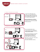
USB 8 sensor interface / Connections II. Connections step 1 Connect your sensor step 2 Connection to your computer 4 3 5 inputs 7 6 8 inputs 1 usb sensorbox 2 4 3 5 7 6 8 inputs inputs ivity s ys t e m ter a c t i ve s e n so r ct 2 in a www.eowave.com 2 in s ys t e m ter a c t i ve s e n so r usb sensorbox ivity step 4 Open your sequencer 1 ct step 3 Open Eobody2 Editor a www.eowave.com 2 II.
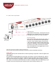
USB 8 sensor interface / Connection to your computer II. 2 Step 2: Connection to your computer sensor computer with Eobody2 editor and other audio software analogue signal 2 5 4 3 7 6 8 inputs inputs in s ys t e m ter a c t i ve s e n so r usb sensorbox ivity 1 ct USB a www.eowave.com 2 USB, FireWire or internal soundcard To connect your Eobody2 to your computer, connect the USB cable to your computer USB in (or to any USB hub connected to your computer).
USB 8 sensor interface / Power II.3. How is the unit powered? 9V DC 220V or 110V AC /9V DC adapter USB powering USB enables self powering. Just plug the usb from Eobody2 to your computer usb in. The red activity LED lights up when the unit is well connected. External powering Some sensors need more than the usb current. In this case, you can power the unit externally with a 9 V DC / 500 mA power supply. Connect the 9 V DC / 500 mA power supply into the power plug connector of Eobody2.
USB 8 sensor interface / Eobody2 editor III. Eobody2 editor III.1. Global parameters window Open the editor One of the first thing you did when you got your Eobody was to download and install the editor. Refer to “Register and Install section if you have not). Double click on the editor icon to open it. The Global parameter window will appear.
USB 8 sensor interface / Eobody2 editor III.3. Eobody2 internal memory configuration check current parameters check the internal memory of Eobody2 unit. save current parameters save current parameters inside the Eobody2 internal memory. Eobody2 has an internal memory to store parameters settings. You may store an entire installation or performance configuration inside one or more Eobody2 and keep it (or them) as back-up units for a future use. init all parameters initialize to factory settings.
USB 8 sensor interface / Internal process & editor parameters Internal process & editor parameters Eobody2 offers a complex internal pre-processing of the data you may set in the editor.
USB 8 sensor interface / Parameters window III.5. Parameters window Open the Parameters window To open the Parameters window, click on the arrow preceeding PARAMETERS. The Parameters window enables to adjust internal processing parameters for each input (1 to 8). Refer to the description of each parameter for use. To increase or decrease parameter values, click on the case you want to edit and slightly move up or down your mouse. Note that all setting parameters changes are made in real time.
USB 8 sensor interface / Parameter window status on/off The status field indicates whether the signal on an analogue input should be converted into a digital message or not. This field may be set to ON or OFF. If the field is set to OFF, the input is said to be inactive and no message relating to that input will be generated, even if a signal does physically enter the device.
USB 8 sensor interface / Parameters window inverse 127 becomes 0 and 0 becomes 127. This way you may inverse the curse of a sensor. With an expression pedal, for example, you’ll be able to inverse its curse. filter 0-64 32 bits low-pass filter that smoothes the signal - for unstable sensors. gate noise gate:12 values [0-11] A noise gate threshold reduces Sensor Noise band the bit depht of the signal.
USB 8 sensor interface / Parameters window Note on message N-ON trigger hi-low The analogue signal must correspond to an envelope changing with time and which has a maximum value. 3 parameters need to be specified: note sent, higher threshold, lower threshold. Eobody2 analyses this envelope: once the envelope has reached the higher threshold, a MIDI note on message (NOTE ON) is generated. The velocity associated with the note is fixed to 127.
USB 8 sensor interface / Formating to host Formating messages to host type This is one of the most important configuration parameters, since it determines which type of MIDI message the device is going to send in response to variations in a particular analogue input.
USB 8 sensor interface / Formating to host message Channel: [1-8] This field enables the user to select a MIDI channel to which the MIDI message will apply (1 to 8). value val: 0 - 127 This field enables the user to set the fixed parameter of a MIDI message associated with an analogue input. This parameter value may correspond to a MIDI note number, a MIDI controller number or a MIDI program number, depending on the type of MIDI message which is chosen.
USB 8 sensor interface / Making my own sensors IV. Making my own sensors eo•body supports many kind of sensors. Most common sensors are switches and potentiometers, but there are many other kinds of sensors. Making my own sensor switch Switch 3-5 Kohm ground + 5V Sensors need a minimum of two cables: ground and signal. When 5 V is connected to the signal - when using switches for example - it may create an antenna effect generating undesirabled distorsion.
USB 8 sensor interface / Making my own sensors Amplification Some sensors have a weak signal out and need amplifying. To avoid undesirable noises, the amplifier should be placed as close as possible from the sensor.
USB 8 sensor interface / List of MIDI controllers V.
USB 8 sensor interface / MIDI Implementation VI.
USB 8 sensor interface / Technical specifications CE norm & FCC INFORMATION 1. Important notice: do not modify this unit! This product, when installed as indicated in the instructions contained in this manual, is compatible with the CE norm & FCC requirements. 2. Important! When connecting this product to accessories and/or another product, use only high quality shielded cables. Cables supplied with this product must be used. Follow all installation instructions.
Other Eobody2 interfaces soon available ethernet 32 in interface... a complete control system for performances, installations...