Eonis User Guide 24–inch clinical display MDRC-2224 WP MDRC-2224 BL K5903081/01 20/01/2014
Barco nv President Kennedypark 35, 8500 Kortrijk, Belgium Phone: +32 56.23.32.11 Fax: +32 56.26.22.62 Support: www.barco.com/esupport Visit us at the web: www.barco.
Table of contents TABLE OF CONTENTS 1. Welcome! .......................................................................................... 3 1.1 1.2 About the product .. .. .. .. .. .. .. .. .. .. .. .. .. .. .. .. .. .. .. .. .. .. .. .. .. .. .. .. .. .. .. .. .. .. .. .. .. .. .. .. .. .. .. .. .. .. . 3 What’s in the box. .. .. .. .. .. .. .. .. .. .. .. .. .. .. .. .. .. .. .. .. .. .. .. .. .. .. .. .. .. .. .. .. .. .. .. .. .. .. .. .. .. .. .. .. .. .. . 4 2. Parts, controls and connectors .....
Table of contents 2 K5903081 EONIS 20/01/2014
1. Welcome! 1. WELCOME! 1.1 About the product Consistent image quality The Eonis display presents crisp, razor-sharp, high-contrast images. To guarantee image consistency at all times, it features a unique front sensor that automatically aligns image quality every time the display is turned on. This image consistency enhances collaboration: images always appear exactly like they are supposed to, on every display, which spurs confident clinical decisions.
1. Welcome! 1.2 What’s in the box Overview Your Eonis comes with: • • • • • • • • • • this Eonis user guide a documentation CD containing multilingual user documentation a system CD containing MediCal QAWeb Agent a (set of) AC power cord(s) (depending on the region of operation) a VGA cable a HDMI cable a DP cable a USB cable an external power supply an accessory bag (cleaning cloth, velcro cable routing strap) Keep your original packaging.
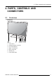
2. Parts, controls and connectors 2. PARTS, CONTROLS AND CONNECTORS 2.1 Front view Overview Image 2-1 1. 2. 3. 4. 5. 6. 7.
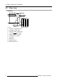
2. Parts, controls and connectors 2.2 Rear view Overview Image 2-2 1. 2. 3. 4. 5. 6. 7. 8. 9. 10.
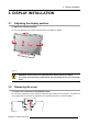
3. Display installation 3. DISPLAY INSTALLATION 3.1 Adjusting the display position To adjust the display position You can now safely pivot, tilt, swivel, raise and lower your display as desired. Image 3-1 WARNING: Put the display in its highest position before pivoting the display. The display will be delivered in portrait mode. Pivot the display 90° to use it in landscape mode. 3.
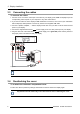
3. Display installation 3.3 Connecting the cables To connect the cables 1. Connect one or more of the video input connections of your display (VGA, HDMI or DisplayPort) to the corresponding video outputs on your computer or any other video device. 2. If you want to make use of the display’s USB downstream connectors, then connect your workstation with the display’s USB upstream connector by means of the supplied USB cable. 3. Connect a speaker, amplifier, ...
3. Display installation Image 3-4 3.5 Routing the cables To route the cables 1. Slide the cable routing strap through the opening in the back of the stand. 2. Bundle all cables together so that they will fit in the strap. 3. Wrap and fix the cable routing strap around all cables. Image 3-5 3.6 Kensington security slots To make use of the Kensington security slots Your Eonis display has 2 Kensington slots available which allow you to secure the display to a desk or any other fixed object.
3. Display installation Image 3-6 3.7 VESA-mount installation To mount the display on a VESA arm The display panel, standard attached to a stand, is compatible with the VESA 100 mm standard. 1. Put the display face down on a clean and soft surface. Be careful not to damage the panel screen. 2. Unscrew the four fixation screws to detach the panel from the stand. 3. Use 4 M4 screws to attach the panel to a VESA approved arm.
3. Display installation CAUTION: Use suitable mounting apparatus to avoid risk of injury.
3.
4. Daily operation 4. DAILY OPERATION 4.1 Recommendations for daily operation Optimize the lifetime of your display Enabling the Display Power Management System (DPMS) of your display will optimize its lifetime by automatically switching off the backlight when the display is not used for a specified period of time. By default, DPMS is enabled on your display, but it also needs to be activated on your workstation. To do this, go to “Power Options Properties” in the “Control Panel”.
4. Daily operation 4.2 On/Off switching To switch your display on or off 1. Shortly press the Standby ( 4.3 ) key. Bringing up the OSD menus About the OSD menu The OSD menu allows you to configure different settings to make your Eonis display fit your needs within your working environment. Also, you can retrieve general information about your display and its current configuration settings through the OSD menu. To bring up the OSD menu 1. While the display is switched on, press the Menu/Enter ( ) key.
5. Advanced operation 5. ADVANCED OPERATION 5.1 Video input source selection About video input source selection By default, your Eonis display automatically detects and shows the connected video input source. However, when for instance more then one video input source is connected, it may be needed to manually select the input source to be displayed.
5. Advanced operation • • • • • Native: If you select Native, the native panel behavior will not be corrected. sRGB: This is the display function as defined in the sRGB specification and is designed to match typical home and office viewing conditions. It is widely used in most computer applications. DICOM: DICOM (Digital Imaging and Communications in Medicine) is an international standard that was developed to improve the quality and communication of digital images in radiology.
5. Advanced operation To select the white point 1. Bring up the OSD main menu. 2. Navigate to the Adjustments menu. 3. Enter the White Point submenu. 4. Select one of the available white point presets. 5.6 Analog video settings The following settings are only available when VGA video input source is selected.
5. Advanced operation 2. Navigate to the Adjustments > Settings menu. 3. Enter the Language submenu. 4. Select one of the available languages. 5.
5. Advanced operation 5.10 Self calibration frequency About self calibration The front sensor of your Eonis display measures the output luminance of your screen and allows the display to automatically stabilize its luminance for maximum image quality over the displays’ lifetime. This self calibration is done at an adjustable, predefined frequency: • • • • • • 1 min 1 hr 6 hr 24 hr Never QAWeb: This setting will be automatically selected when the self calibration frequency is defined by MediCal QAWeb.
5.
6. Maintenance 6. MAINTENANCE General maintenance information The Eonis does not require any scheduled maintenance or calibration activities. We recommend to use QAWeb with the Barco default tests and frequencies to calibrate and maintain the display or return the display to a Barco approved maintenance organization. In any case of doubts, contact the Barco Healthcare Division 6.
6.
7. Important information 7. IMPORTANT INFORMATION 7.1 Safety information General recommendations Read the safety and operating instructions before operating the device. Retain safety and operating instructions for future reference. Adhere to all warnings on the device and in the operating instructions manual. Follow all instructions for operation and use. Electrical Shock or Fire Hazard To prevent electric shock or fire hazard, do not remove cover. No serviceable parts inside.
7. Important information To fully disengage the power to the device, please disconnect the power cord from the AC inlet. Power cords: • • • • • Utilize a UL-listed detachable power cord, 3-wire, type SJ or equivalent, 18 AWG min., rated 250 V min., provided with a hospital-grade type plug 5-15P configuration for 120V application, or 6-15P for 240V application. Do not overload wall outlets and extension cords as this may result in fire or electric shock. Mains lead protection (U.S.
7. Important information Norway: "Apparatet må tilkoples jordet stikkontakt" Sweden: "Apparaten skall anslutas till jordat uttag" 7.2 Environmental information Disposal Information Waste Electrical and Electronic Equipment This symbol on the product indicates that, under the European Directive 2012/19/EU governing waste from electrical and electronic equipment, this product must not be disposed of with other municipal waste.
7. Important information • • • • Reorient or relocate the receiving antenna. Increase the separation between the device and receiver. Connect the device into an outlet on a circuit different from that to which the receiver is connected. Consult the dealer or an experienced radio/TV technician for help. Changes or modifications not expressly approved by the party responsible for compliance could void the user’s authority to operate the equipment.
7. Important information Electromagnetic immunity The Eonis is intended for use in the electromagnetic environment specified below. The customer or the user of the Eonis should assure that it is used in such an environment.
7. Important information Immunity test IEC 60601 Electromagnetic environment – guidance Compliance level Test levels d = 2.3√P 800 MHz to 2.5 Ghz Where P is the maximum output power rating of the transmitter in watts (W) according to the transmitter manufacturer and d is the recommended separation distance in meters (m). Field strengths from fixed RF transmitters, as determined by an electromagnetic site survey,3 should be less than the compliance level in each frequency range.
7. Important information Rated maximum output Separation distance according to frequency of transmitter power of transmitter 5 150kHz to 80MHz 80MHz to 800MHz 800MHz to 2.5GHz W d=1.2√P d=1.2√P d=2.3√P 0.01 0.12 0.12 0.23 0.1 0.38 0.38 0.73 1 1.2 1.2 2.3 10 3.8 3.8 7.3 100 12 12 23 At 80 MHz and 800 MHz, the separation distance for the higher frequency range applies. These guidelines may not apply in all situations.
7.
7. Important information Stand-by Equipotentiality Symbols on the box On the box of the device, you may find the following symbols (nonrestrictive list): Indicates a device that can be broken or damaged if not handled carefully when being stored. Indicates a device that needs to be protected from moisture when being stored. Indicates the storage direction of the box. The box must be transported, handled and stored in such a way that the arrows always point upwards.
7. Important information Barco Inc. and the licensee. No other use, duplication, or disclosure of a Barco software product, in any form, is authorized. The specifications of Barco products are subject to change without notice. Trademarks All trademarks and registered trademarks are property of their respective owners. Copyright notice This document is copyrighted. All rights are reserved.
7. Important information Dimensions with stand (W x H x D) Dimensions w/o stand (W x H x D) Dimensions packaged (W x H x D) Net weight with stand 560.4 x 533 x 164.45 mm 560.4 x 366 x 59.82 mm 481 x 273 x 761 mm 8.38 kg Net weight w/o stand Net weight packaged with stand Height adjustment range 5 kg Tilt -5° / +20° Swivel Pivot -45° / +45° Yes Mounting standard VESA (100 mm) Screen protection N/A Certifications CE (MDD 93/42/EEC class I product), CE - 2004/108/EC, IEC 60601-1 (ED.
7. Important information Pixel pitch 0.270 Color imaging Yes Gray imaging Yes Color support 16,7 million colors Viewing angle (H, V) 178° Ambient Light Compensation (ALC) Front sensor Yes, preset values in OSD Yes Maximum luminance 300 cd/m² typical DICOM calibrated luminance 180 cd/m² 1000:1 typical Contrast ratio Response time (Tr + Tf) Housing color 14 ms typical Video input signals USB ports VGA, DisplayPort, HDMI 1 upstream, 2 downstream USB standard 2.
7. Important information Supplied accessories User Guide Cable routing strap Video cables (1 x VGA + 1 x HDMI + 1 x DP) Main cables (UK, European (CEBEC/KEMA) or USA (UL/ CSA; adaptor plug NEMA 5-15P)) USB 2.0 cable This adapter(s) is a forming part of the medical device. QA software Warranty (Manufacturer: BridgePower Corp.; model: BPM060S12F03; Input: ), 5.0 A) 100-240 V AC, 50-60 Hz, 1.5 A; Output: +12V DC ( QAWeb Private Practice, QAWeb 1.
7.
A. Troubleshooting A. TROUBLESHOOTING A.1 Troubleshooting General If you experience trouble with the LCD display, refer to the following troubleshooting. If the problem persists, please contact your local dealer or our service center. Problem: No image appears on the screen • • • Push the standby button. Check if all I/O and power connectors are correctly connected as described in the “installation” section. Make sure the pins of the connectors are not crooked or broken.
A. Troubleshooting Problem: Out of range This message means that the signal of the computer graphics card is not compatible with the display. When the signal is not included in the compatibility mode we have listed in the appendices of this manual, the display will show this message.