
Specifications

23
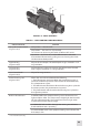
C
D
E
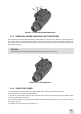
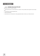
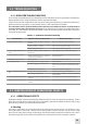
FIGURE 39. SIRIUS CONTROLS
B
A
TABLE 31. SIRIUS CONTROLS AND INDICATORS
CONTROL/INDICATOR FUNCTION
Turn-pull Function Switch
(Figure 3-10, A)
OFF position — the unit is o.
ON position — the unit is on (IT powered).
Turn the unit on by turning the switch CCW from OFF to ON.
IR position — the unit is on, and the IR illuminator is activated.
Activate the IR illuminator by pulling it out and turning the switch
CW from ON to the IR position.
Eyepiece Ring
(Figure 3-10, B)
Adjusts the unit diopter. The total dioptric range is covered in a 1/2
ring revolution.
Focusing Ring
(Figure 3-10, C)
Focuses the lens. Adjusts for sharpest view of the scene. The total
focus range is covered in a 1/3 ring revolution.
Gain Control Knob*
(Figure 3-10, D)
Adjusts for image contrast.
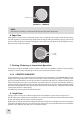
Pivotal Focusing Lens
(Figure 3-10, E)
Allows the user to choose between the following:
1. The IR illuminator spot beam. When the pivotal focusing lens is
placed in the leftmost position of the window of the IR illuminator,
the photoreceiver is open.
2. The IR illuminator ood beam. When the focusing lens is placed in
the center position, the photoreceiver is opened.
3. The photoreceiver will close when the focusing lens is placed in
the rightmost position.
Built-in LED Indicators A GREEN GLOW in the eyepiece viewing area indicates excessive
light conditions. After 10 s of exposure to bright light, the intensier
will shut o automatically. The unit will turn back on again when
moved away from the excessive light.
A PERMANENT RED GLOW in the eyepiece viewing area indicates
that the IR illuminator is operating.
A FLASHING RED LIGHT in the eyepiece viewing area indicates that
the battery is low.
* For Sirius-M version only.