
air handler User's Manual


7
ENVISION SERIES AIR HANDLER INSTALLATION MANUAL
General Installation Information
Air Handler Installation
The air handler is attached to the shipping pallet with
screws. Prior to setting the unit in place remove the ship-
ping screws located in the front base right behind the air
filter access panel. Also remove the external shipping brack-
ets at the rear of the cabinet.
An air filter must always be installed upstream of the air
coil on the return air side of the air handler. An air filter is
provided with the air handler. If there is limited access to
the filter rack for normal maintenance, it is suggested that
a return air filter grille be installed. In this instance the filter
supplied with the air handler should be removed. Be sure
that the return duct is properly installed and free of leaks to
prevent dirt and debris from bypassing the filter and plug-
ging the air coil.
The cabinet should be sealed so that unconditioned warm
air can not enter the cabinet. Warm air will introduce mois-
ture into the cabinet which could result in water blow-off
problems, especially when installed in an unconditioned
space. Make sure that the liquid line, suction line and drain
line entry points into the cabinet are well sealed. Use the
butyl tape supplied with the air handler to seal around the
copper lines entering the cabinet.
All wall penetrations should be sealed properly. The line
set should not come into direct contact with water pipes,
floor joists, wall studs, duct work, floors, walls and brick.
The line set should not be suspended from joists or studs
with a rigid wire or strap which comes into direct contact
with the tubing. Wide hanger straps which conform to the
shape of the tubing are recommended. All line sets should
be insulated with a minimum of 3/8” closed cell insula-
tion. The line set insulation should be pliable, and should
completely surround the refrigerant line. As in all R-410a
equipment, a reversible liquid line filter drier is required to
insure all moisture is removed from the system. This drier
is factory installed in the Envision Split series compressor
section. This drier should be replaced whenever “breaking
into” the system for service. All exterior insulation should
be painted with UV resistant paint or covering to insure
long insulation life.
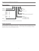
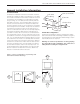
Connection to the Coil
Connect the refrigerant line set to the ‘A’ coil tubes. Nitro-
gen should be bled through the system at 2 to 3 PSI to pre-
vent oxidation inside the refrigerant tubing. Use a low silver
phos-copper braze alloy on all brazed connections. The air
handler txv bulb is secured to the ‘A’ coil for shipping. The
Envision Split series compressor section is shipped with a
factory charge and the service valves are not to be opened
until the line set and air handler have been leak tested,
purged and evacuated. A damp towel or heat sink should
be used on the service valves to prevent damage caused by
excessive heat.
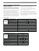
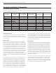
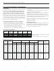
Refer to the Refrigerant Line Sizing table to determine the
proper line set configuration for the system being installed.
Line sets over 60 feet in length are not recommended. If
the line set is kinked or deformed and cannot be reformed,
the bad section of pipe should be replaced. A restricted
line set will affect unit performance. Line sets should be
routed as directly as possible, avoiding any unnecessary
bends and turns.
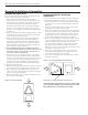
Important Note:
The bulb will need to be attached to the suction line on the
outside of the cabinet once the refrigerant line connections
have been made.
Leak Testing
The refrigeration line set must be pressurized and checked
for leaks before purging and charging the unit. To pres-
surize the line set, attach refrigerant gauges to the service
ports and add an inert gas (nitrogen or dry carbon dioxide)
until pressure reaches 60 to 90 PSIG. Never use oxygen or
acetylene to pressure test the system. Use an electronic
leak detector or a good quality bubble solution to detect
leaks on all connections made in the field. Be sure to check
the service valve ports and stems for leaks. If a leak is
found, repair it and repeat the above steps. For safety rea-
sons do not pressurize the system above 150 PSIG. Purge
pressure from the line set slowly when the pressure test is
complete. The system is now ready for evacuation.
System Evacuation
Ensure that the line set and air coil are evacuated before
opening service valves. The line set and air coil must be
evacuated to 250 microns with a good quality vacuum
pump and use a vacuum gauge to ensure that air and
moisture are removed. With the system shut off from the
vacuum pump a sufficient system vacuum is achieved when
a 500 micron vacuum can be held for 30 minutes. A fast
rise to atmospheric pressure indicates a leak, while a slower
rise to around 1500 microns indicates moisture is still pres-
ent in the system and further evacuation is required.