
air handler User's Manual


6
ENVISION SERIES AIR HANDLER INSTALLATION MANUAL
Bottomflow Application
To convert the NAH series air handlers for bottomflow ap-
plications follow the steps shown below:
Remove all access panels. Disconnect the blower
harnesses from the motor and loosen ground wire from
blower. Remove the blower by removing 2 screws from
the blower mounting bracket, and slide the blower
assembly out the front. Remove the stiffener bracket in
front of coil, 'A' coil/pan assembly and the horizontal
drain pan. This will lighten the cabinet and make it easier
to maneuver.
Rotate the cabinet 180° from the upright position so that
the discharge air opening is located at the bottom and
the return air opening is at the top.
Install the blower assembly into the blower discharge
opening at the bottom of the cabinet by sliding the
blower mounting bracket under the discharge support
bracket and secure in place with 2 screws. The blower
harness and motor ground wire should be reattached
before sliding the blower into place.
On the NAH042-060 install the NAHBC bottomflow
conversion kit per instructions in the kit. Failure to install
this kit will result in condensate blow-off from the 'A'
coil into the cabinet and ductwork.
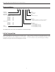
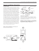
Install the 'A' coil into the upper section of the cabinet
as pictured in Figure 2. Attach the stiffener bracket into
the two holes provided in the cabinet so that the bracket
is in front of the coil. The horizontal drain pan is not
needed and must be discarded. Plug the 2 drain hole
openings in the access panel with the plugs provided.
Replace the access panels.
Bottom air discharge units require the supply air opening
to be cut at least a 1/2” larger than the unit’s air outlet.
When installed on combustible flooring, protect the
edges of the floor opening with sheet metal over wrap or
other non-combustible material.
Bottom air discharge units should be sealed well to the
floor to prevent air leakage.
1.
2.
3.
4.
5.
6.
7.
8.
9.
Horizontal Right Air Discharge
Application
To convert the NAH series air handlers for horizontal right
air discharge applications follow the steps shown below
Remove all access panels. Remove the stiffener bracket
in front of the coil, ‘A’ coil assembly and the horizontal
drain pan.
From the vertical upflow position, rotate the top of the
cabinet 90° to the right and set in place.
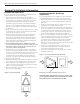
Remove the support bracket mounted to the top plate of
the ‘A’ coil. Rotate the ‘A’ coil support bracket 180° from
its original position and re-attach into existing holes in
the top plate of the coil. This must be done to prevent
the ‘A’ coil from falling into the drain pan (Figure 3).
Move the horizontal drain pan from the left side of the ‘A’
coil to the right hand side of the ‘A’ coil. Place the ‘A’ coil
and horizontal drain pan assembly into the cabinet
so that the support bracket is resting in the horizontal
drain pan as shown in Figure 3. Attach the stiffener
bracket into the two holes provided in the cabinet so that
the bracket is in front of the coil.
Remove the 2 drain plugs from the upper right of the
access panel and install them on the lower left of the
access panel. Replace the access panels.
If the unit is suspended, the entire length of the cabinet
should be supported.
Important: When removing the coil, there is possible dan-
ger of equipment damage and personal injury. Be careful
when removing the coil assembly from the unit.
1.
2.
3.
4.
5.
6.
Figure 2 - Bottomflow NAH.
Figure 3 - Horizontal Right Hand Air Discharge
Rotate the coil support bracket to this position
General Installation Information