
air handler User's Manual


4
ENVISION SERIES AIR HANDLER INSTALLATION MANUAL
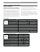
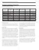
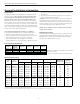
Air Handler Sizing Selection
The Envision Air Handlers are designed for R410a refrigerant and should be matched with Envision Split series compressor
section according to the table below.
General Installation Information
Moving and Storage
If the equipment is not needed for immediate installation it
should be left in its shipping carton and stored in a clean,
dry area. Units must only be stored or moved in the normal
“up” orientation.
Unit Location
Locate the unit in an indoor area that allows for easy re-
moval of the filter and access panels (the air handler units
are not approved for outdoor installation). Location should
have enough space for service personnel to perform main-
tenance or repair. Provide sufficient room to make refriger-
ant, electrical and duct connections. If the unit is located
in a confined space, such as a closet, provisions must be
made for return air to freely enter the space by means of a
louvered door, etc. The air handler section may be installed
on any level surface strong enough to support its weight.
When installed in a closet or on a stand, it should be
mounted on vibration absorbing material slightly larger than
the base to minimize vibration transmission to the building
structure.
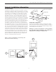
When installed in an attic or above a drop ceiling, the instal-
lation must conform to all local codes. If the unit is sus-
pended and installed in the horizontal position, the entire
length of the unit should be supported. If the application
requires the air handler to be installed on the attic floor
then the unit should be set in a full size secondary drain
pan. In this case the secondary drain pan should be set on
top of a vibration absorbing mesh. The secondary drain
pan is usually placed on a plywood base. A secondary drain
pan should be used when equipment is installed over a
finished living area to provide protection from water dam-
age in case of plugging of the air handler primary drain line.
The secondary drain line should terminate somewhere that
is easily visible by the homeowner. Be certain to show the
homeowner the termination location of the secondary drain
line and to explain its purpose.
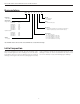
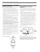
Duct System
The duct system should be sized to handle the design air-
flow quietly and efficiently. To maximize sound attenuation
of the unit blower, the supply and return plenums should
include an internal duct liner of fiberglass or constructed
of ductboard for the first few feet. On systems employing
a metal duct system, canvas connectors should be used
between the unit and the ductwork. If air noise or exces-
sive airflow is a problem, the blower speed can be changed.
Application of the unit to un-insulated metal ductwork in an
unconditioned space will cause poor unit performance and
allow condensation to form on the duct and possibly cause
damage to the structure.
If the unit is connected to existing ductwork, check the duct
system to ensure that it has the capacity to accommodate
the air required for the unit application. If the duct is too
small, as in the replacement of heating only systems, larger
ductwork should be installed. All existing ductwork should
be checked for leaks and repaired as necessary.
Air Handler
Indoor Split Model
(Single)
Indoor Split Model
(Dual Capacity)
Outdoor Split Model
(Dual Capacity)
Airfl ow(CFM) Electric Heat (kW)
NAH022A***1R
NSZ022 - 800 5
NAH026A***1R
- NDZ026 NDS026 925 5
NAH030A***1R
NSZ030 - - 980 5, 10
NAH036A***1R
NSZ036 - - 1225 5, 10
NAH036A***1R
- NDZ038 NDS038 1225 5, 10
NAH042A***1R
NSZ042 - - 1425 10, 15
NAH048A***1R
NSZ048 - - 1625 10, 15
NAH048A***1R
- NDZ049 NDS049 1625 10, 15
NAH060A***1R
NSZ060 - - 1760 10, 15, 20
NAH060A***1R
- NDZ064 NDS064 1760 10, 15, 20
NAH060A***1R
NSZ070 - - 1760 10, 15, 20
NAH060A***1R
- NDZ072 NDS072 1760 10, 15, 20
6/9/08