
air handler User's Manual


19
ENVISION SERIES AIR HANDLER INSTALLATION MANUAL
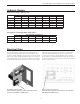
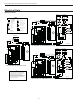
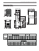
Dimensional Data
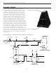
Bottom Flow Unit Configuration
Overall Cabinet
Bottomflow
DEF
Configuration
ABC
3/4" cond 1" cond Return
GH I JK L M NOPQR
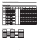
Width Depth Height
Low
Voltage
Power
Supply
Air Duct
Flange
Suction /
Water Out
Liquid /
Water In
in. 21.0 26.1 57.3 5.1 3.3 0.7 58.1 27.4 28.3 51.6 49.1 41.2 34.6 29.2 28.6 6.1 4.2 0.9
cm. 53.4 66.3 145.6 12.9 8.5 1.8 147.4 69.6 71.8 131.1 124.7 104.7 87.9 74.2 72.7 15.4 10.8 2.4
Condensate is stainless steel 3/4" FPT
Rev:A 3/12/08
Discharge flange is field installed and extends 1" (25.4 mm) from cabinet
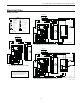
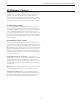
Refrigerant/Water
Connections
022-060
CC DD
EE
STUVW
XYZAA
BB
1" cond
FF GG
HH
II JJ
KK LL MM
Power
Supply
1.5 10.5 15.5 18.0 19.5 20.1 59.1 15.1 32.6 30.1 2.0 2.0 2.0 18.0 1.5 18.0 1.5 22.1 2.0 16.9
1.96
3.9 26.7 39.4 45.8 49.5 51.0 150.0 38.4 82.8 76.5 5.1 5.1 5.1 45.7 3.8 45.7 3.8 56.2 5.0 42.9 5.0
1/2" cond
Low Voltage
@756BA723D73E
Y
G
C
E
D
I
B
H
0.71 F
4@=<BD73E
Q
P
O
N
M
L
K
J
BB
AA
Z
R
S
T
U
V
W
X
A
0=BB=;D73E
HH II
GG
FF
DD
EE
CC
B=>D73E
JJ
LL
KK
MM