
air handler User's Manual


11
ENVISION SERIES AIR HANDLER INSTALLATION MANUAL
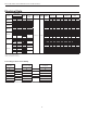
Hydronic Models
Flow gpm
Pressure Drop (PSI)
40°F 50°F 60°F 100°F 110°F 120°F 130°F
3.0 0.5 0.5 0.5 0.4 0.4 0.4 0.4
4.5 0.9 0.9 0.9 0.8 0.8 0.8 0.8
6.0 1.4 1.4 1.4 1.2 1.2 1.2 1.2
9.0 2.8 2.6 2.5 2.4 2.4 2.4 2.3
12.0 4.6 4.4 4.2 4.0 4.0 4.0 3.9
15.0 7.0 6.8 6.6 6.0 6.0 5.9 5.8
Water Presure Drop - Hydronic Coil
Entering Water Temperature °F
EAT °F 100 110 120 130 140 150
65
44% 56% 69% 81% 94% 106%
70
37% 50% 63% 75% 87% 100%
Coil Capacity vs. Entering Water Temperature
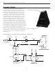
Electrical Data
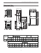
All field wiring must comply with local and national fire,
safety and electrical codes. Be sure the available power is
the same voltage and phase as that shown on the unit serial
plate. Refer to the unit Electrical Data table for fuse and cir-
cuit breaker sizing. The thermostat should be connected to
the air handler and to the compressor section. Line voltage
power should be supplied to the breakers on air handlers
with 15kW and 20kW heater kits (see the electric heat
control section picture). On air handlers with no electric
heat installed, or with 5kW and 10kW heater kits the power
should be supplied to L1 and L2 lugs on PB (see air handler
control section picture).
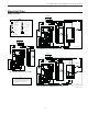
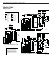
Air Handler Control Section:
Power should be supplied to PB on air handlers with no
electric heat and 5kW or 10kW heaters.
Electric Heat Control Section:
Power should be supplied to the breakers on air handlers
with 15kW and 20kW heaters.