
Installation Guide

26
Removing and Replacing the Gas Control Valve/
Thermostat:
IMPORTANT: The gas control valve/thermostat is a standard valve
with a right hand thread thermocouple. Use only factory authorized
replacement parts.
Removing the Gas Valve:
1. Turn the gas control knob on the combination gas control
valve/thermostat clockwise to the “OFF” position. See “Lighting
Instructions” on water heater.
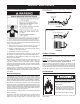
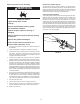
2. Turn off the gas at the manual shut-off valve on the gas supply
pipe (Figure 1).
3. Drain the water heater. Refer to the “Draining and Flushing”
section and follow the procedure.
4. Disconnect the igniter wire from the igniter. Note: There are two
types of igniters. If you have the round igniter, rst remove the
igniter from the bracket by depressing front and rear holding tabs
and lift. Next remove igniter bracket from the gas valve. If you
have the square igniter slide the igniter bracket backwards away
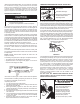
from the gas valve to remove it. Disconnect the thermocouple
(right-hand threads), pilot tube and manifold tube at the gas
control valve/thermostat (Figure 21).
5. Refer to “Gas Piping” section (Figure 14) and disconnect the
ground joint union in the gas piping. Disconnect the remaining
pipe from the gas control valve/thermostat.
6. To remove the gas control valve/thermostat, thread a correctly
sized pipe into the the inlet and use it to turn the gas valve
(counterclockwise). Do not use a pipe wrench or equivalent to
grip body. Damage may result causing leaks. Do not insert any
sharp objects into the inlet or outlet connections. Damage to
the gas control valve/thermostat may result.
Replacing the Gas Valve:
To replace the gas control valve/thermostat, reassemble in reverse
order. When replacing the gas control valve/thermostat, thread a
correctly sized pipe into the inlet and use it to turn the gas control valve/
thermostat (clockwise). DO NOT OVERTIGHTEN, damage may result.
• Be sure to use approved Teon
®
tape or pipe joint compound on the
gas piping connections and tting on the back of the gas control
valve/thermostat that screws into the tank.
• Be sure to remove the pilot ferrule nut from the new gas control
valve/thermostat.
• Turn the gas supply on and check for leaks. Test all connections
by brushing on an approved noncorrosive leak-detection solution.
Bubbles will show a leak. Correct any leak found.
• Be sure tank is completely lled with water before lighting and
activating the water heater. Follow the “Lighting Instructions”.
• If additional information is required, contact the Service
Department at: 1-800-999-9515
TEFLON
®
is a registered trademark of E.I. Du Pont De Nemours and Company.
Operational Checklist
1. Burner door gasket properly sealed.
2. Viewport not damaged or cracked.
3. No leaks at pilot and manifold connection.
4. Burner door screws securely tightened.
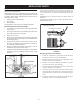
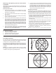
FlueBafeInstallation:
For 100 gallon unit, baffle tab extensions should be oriented
toward the outside of the heater when installed correctly. Refer
to Figure 24 for correct placement of baffles.
For 75 gallon unit, baffle tabs (one each near the top of each
baffle) should be oriented toward the inside of the heater when
installed correctly. Refer to Figure 25 for correct placement
of baffles.
NOTE: Do not operate this water heater unless the baffles
are installed correctly. Failure to do so can result in poor
combustion and high flue gas temperatures.
Bae Tab
Extentions
FIGURE 24
FIGURE 25