
Installation Guide


16
GAS PIPING
Contact your local gas service company to ensure that adequate
gas service is available and to review applicable installation codes
for your area.
Size the main gas line in accordance with Table 3. The gures shown
are for straight lengths of pipe at 0.5 in. W.C. pressure drop, which
is considered normal for low pressure systems. Note: Fittings such
as elbows, tees and line regulators will add to the pipe pressure
drop. Also refer to the current edition of the National Fuel Gas Code
(NFPA 54).
Make sure gas supplied is same type listed on model rating plate.
The inlet gas pressure must not exceed 14 inch water column (2.6
kPa) for natural and propane (L.P.) gas. The minimum inlet gas
pressure shown on rating plate is that which will permit ring at
rated input.
If the gas control valve is subjected to pressures exceeding 1/2 pound
per square inch (3.5 kPa), the damage to the gas control valve could
result in a re or explosion from leaking gas.
If the main gas line shut-off serving all gas appliances is used, also
turn “off” the gas at each appliance. Leave all gas appliances shut
“off” until the water heater installation is complete.
A gas line of sufcient size must be run to the water heater. Consult
the current edition of National Fuel Gas Code ANSI Z223.1/NFPA 54
and your gas supplier concerning pipe size.
There must be:
• A readily accessible manual shut off valve in the gas supply line
serving the water heater, and
• A sediment trap ahead of the gas control valve to help prevent dirt
and foreign materials from entering the gas control valve.
• A exible gas connector or a ground joint union between the shut
off valve and control valve to permit servicing of the unit.
Be sure to check all the gas piping for leaks before lighting the water
heater. Use a soapy water solution, not a match or open ame. Rinse
off soapy solution and wipe dry.
The minimum inlet gas pressure shown on the rating plate is that
which will permit ring at the rated input.
TABLE3.GASSUPPLYLINESIZES(ININCHES)*
MAXIMUM CAPACITY OF PIPE IN CUBIC FEET PER HOUR
LENGTH
IN
FEET
NOMINALIRONPIPESIZES(
INCHES
)
INPUTINTHOUSANDS(BTU/HR)
1/2" 3/4" 1" 1 1/4" 1 1/2" 2" 2 1/2" 3" 4"
10 175 360 680 1400 2100 3960 6300 11000 23000
20 120 250 465 950 1460 2750 4360 7700 15800
30 97 200 375 770 1180 2200 3520 6250 12800
40 82 170 320 660 990 1900 3000 5300 10900
50 73 151 285 580 900 1680 2650 4750 9700
60 66 138 260 530 810 1520 2400 4300 8800
70 61 125 240 490 750 1400 2250 3900 8100
80 57 118 220 460 690 1300 2050 3700 7500
90 53 110 205 430 650 1220 1950 3450 7200
100 50 103 195 400 620 1150 1850 3250 6700
125 44 93 175 360 550 1020 1650 2950 6000
150 40 84 160 325 500 950 1500 2650 5500
175 37 77 145 300 460 850 1370 2450 5000
200 35 72 135 280 430 800 1280 2280 4600
TABLE 4.
LENGTH
IN
METERS
NOMINALIRONPIPESIZES(
INCHES
)
INPUT IN KW
1/2" 3/4" 1" 1 1/4" 1 1/2" 2" 2 1/2" 3" 4"
3 51 105 199 410 615 1160 1845 3221 6735
6 35 73 142 278 428 805 1277 2255 4626
9 28 59 110 225 346 644 1031 1830 3748
12 24 50 94 193 290 556 878 1552 3192
15 21 44 83 170 264 492 776 1391 2840
18 19 40 76 155 237 445 703 1259 2577
21 18 37 70 143 220 410 659 1142 2372
24 17 35 64 135 202 381 600 1083 2196
27 16 32 60 126 190 357 571 1010 2108
31 15 30 57 11 7 182 337 542 952 1962
38 13 27 51 105 161 299 483 864 1757
46 12 25 47 95 146 278 439 776 1610
53 11 23 42 88 135 249 401 717 1464
61 10 21 40 82 126 234 375 688 1347
Use pipe joint compound or teon tape marked as being resistant to
the action of petroleum [Propane (L.P.)] gases.
The water heater and its gas connection must be leak tested before
placing the water heater in operation.
The water heater and its individual shut-off valve shall be
disconnected from the gas supply piping system during any pressure
testing of that system at test pressures in excess of 1/2 pound per
square inch (3.5 kPa). It shall be isolated from the gas supply piping
system by closing its individual manual shut-off valve during any
pressure testing of the gas supply piping system at test pressures
equal to or less than 1/2 pound per square inch (3.5 kPa).
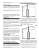
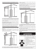
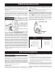
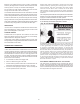
Connecting the gas piping to the gas control valve of the water heater
can be accomplished by either of the two methods shown in Figures
15 and 16.
FIGURE 15. GAS PIPING WITH FLEXIBLE CONNECTOR.
FIGURE 16. GAS PIPING WITH ALL
BLACK IRON PIPE TO GAS CONTROL.